

Joint signal-routing and power-control for an optical network
- Summary
- Abstract
- Description
- Claims
- Application Information
AI Technical Summary
Benefits of technology
Problems solved by technology
Method used
Image

Examples
Embodiment Construction
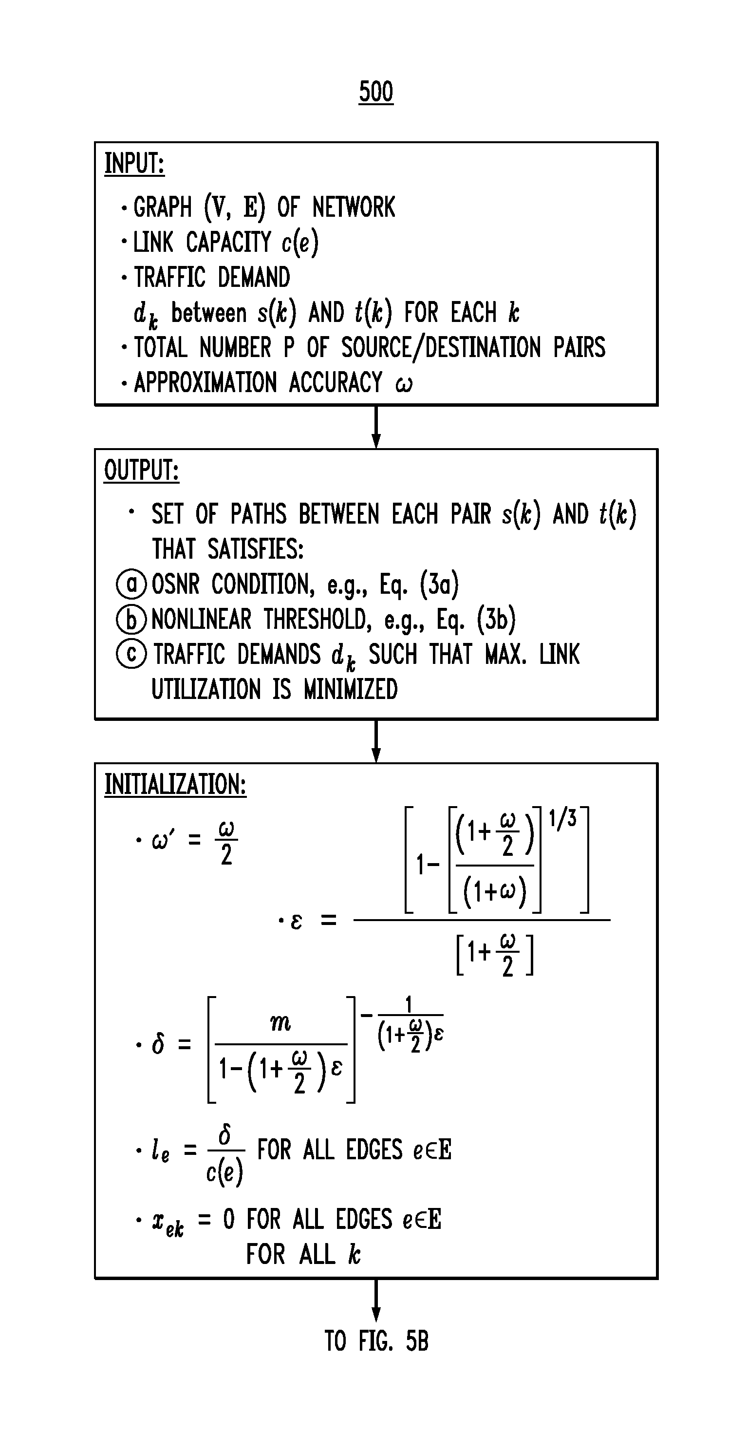
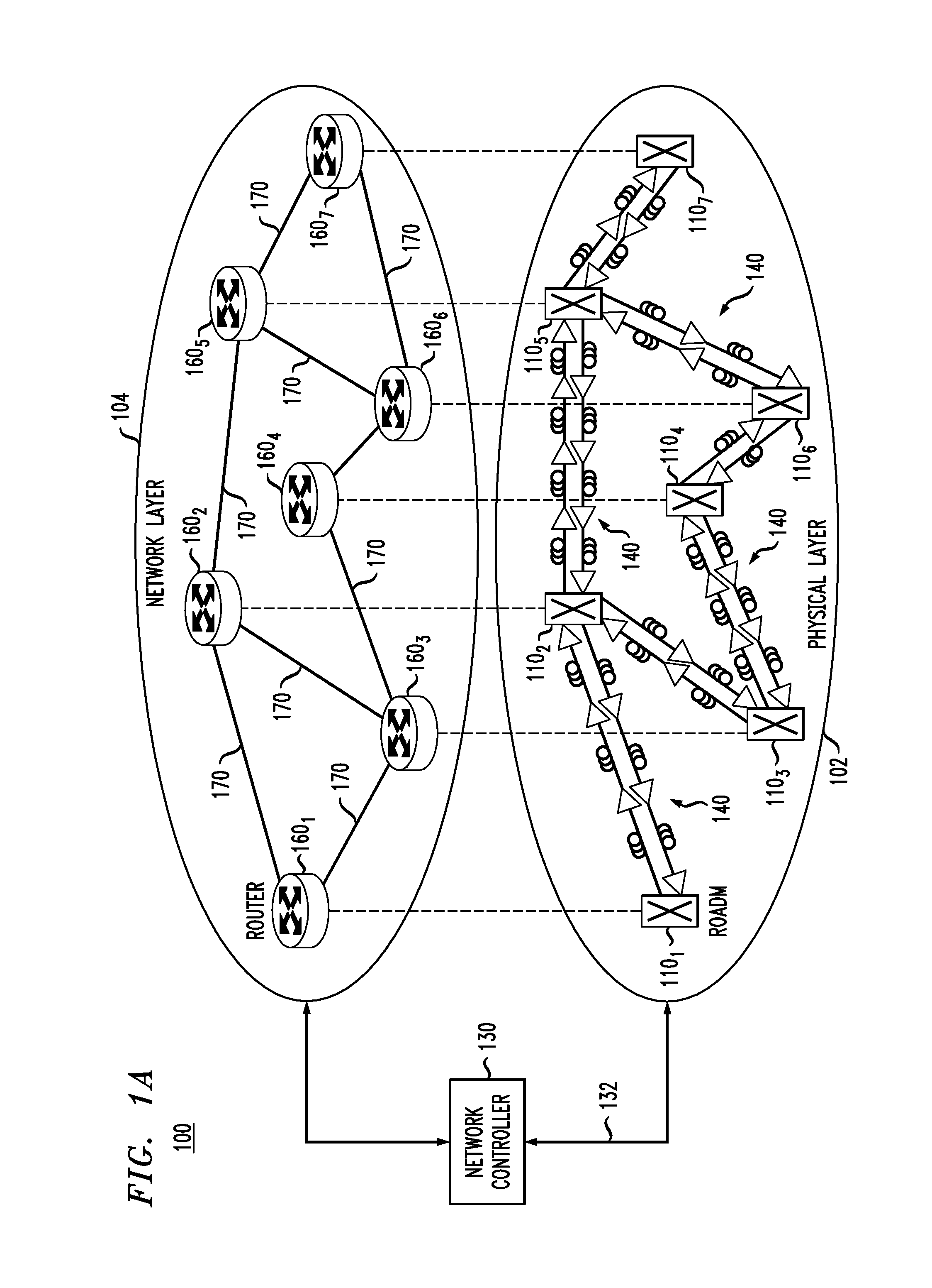
[0007]Disclosed herein are various embodiments of a signal-routing method directed at improving (e.g., optimizing) the throughput of an optical network by taking into account the fiber nonlinearity in the process of solving a joint signal-routing and power-control problem for the optical network. Based on the obtained solution, a network controller may set the signal-routing configurations of the various network nodes and the optical gains of the various optical amplifiers to enable the optical network to carry the traffic in a manner that results in a higher throughput than that achievable with the use of conventional signal-routing and / or power-control methods.
[0008]According to one embodiment, provided is an optical communication method comprising the steps of: determining a plurality of optical paths for a traffic matrix to be routed through an optical network, wherein each optical path of the plurality satisfies a feasibility condition defined by a first threshold value and a s...
PUM
 Abstract
Description
Claims
Application Information