Fluid dynamic vent dam

a dynamic vent dam and fluid flow technology, applied in the direction of fuel tank safety measures, power plant fuel tanks, aircraft power plants, etc., can solve the problems of turbulence and pressure drop or loss, fuel flow can impinge on the vent dam, and high structural loads, so as to prevent or minimize turbulence, improve fluid flow, and efficiently and smoothly dir

Active Publication Date: 2015-04-21
THE BOEING CO
View PDF10 Cites 14 Cited by
  • Summary
  • Abstract
  • Description
  • Claims
  • Application Information

AI Technical Summary

Benefits of technology

[0009]This need for an improved vent dam configuration and method for use in a vent stringer system is satisfied. Unlike known vent dams, embodiments of the vent dam configuration and method may provide numerous advantages. The vent dam configuration and method provides an improved vent dam and method where the vent dam has a guiding surface that may be curved or sloped for efficiently and smoothly directing and improving fluid flow, such as fuel flow and vapor flow, in a vent stringer system. The vent dam configuration and method provides an improved vent dam and method that prevents or minimizes turbulence in a fluid flow, such as fuel flow and vapor flow, in a vent stringer, thus, reducing pressure drop or loss and resulting in an increased refuel rate. The vent dam configuration and method provides a vent dam and method where the vent dam is located relative to a vent stringer access opening and relative to a fluid flow, such as a fuel flow or vapor flow, so as to optimize the fluid flow into and out of the vent stringer. The vent dam configuration and method provides an improved vent dam and method where the vent dam may be comprised of one piece or multiple pieces to enable easy access of the vent dam through the vent stringer access opening, to eliminate the need for blind fasteners, and to allow for effective sealant application, thus resulting in efficient installation, fastening, and sealing of the vent dam within the vent stringer.

Problems solved by technology

Moreover, when the fuel flow enters the vent stringer, the fuel flow can impinge on the vent dam.
Such fuel flow impingement on the upper wing skin and the vent dam, as well as an instantaneous 90 degree change of flow direction can result in turbulence and pressure drop or loss.
Such pressure drop or loss can result in higher structural loads and a decreased refuel rate.

Method used


Image

  • Fluid dynamic vent dam
  • Fluid dynamic vent dam
  • Fluid dynamic vent dam

Examples


Embodiment Construction

[0055]Disclosed embodiments will now be described more fully hereinafter with reference to the accompanying drawings, in which some, but not all of the disclosed embodiments are shown. Indeed, several different embodiments may be provided and should not be construed as limited to the embodiments set forth herein. Rather, these embodiments are provided so that this disclosure will be thorough and complete and will fully convey the scope of the disclosure to those skilled in the art.

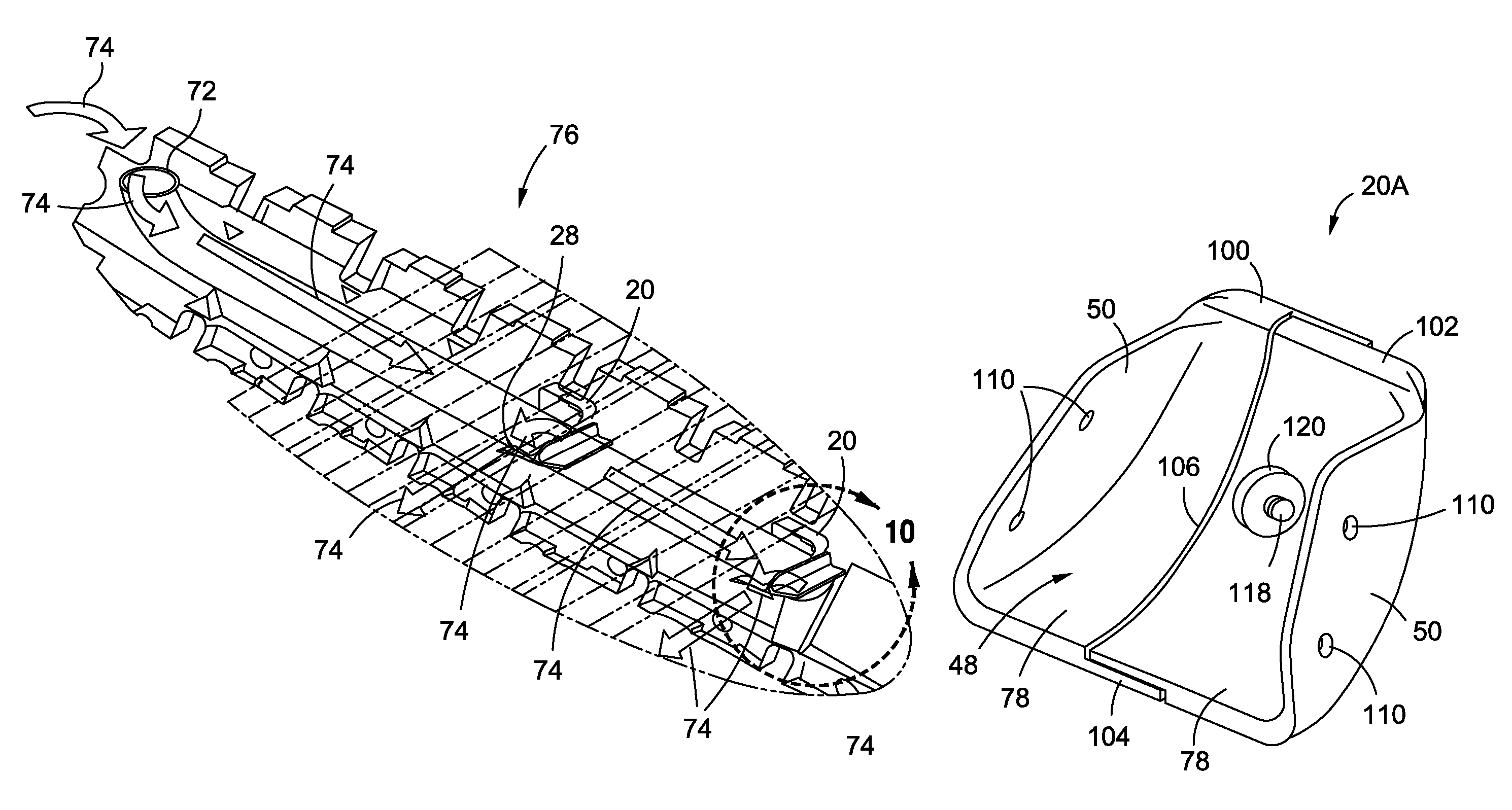
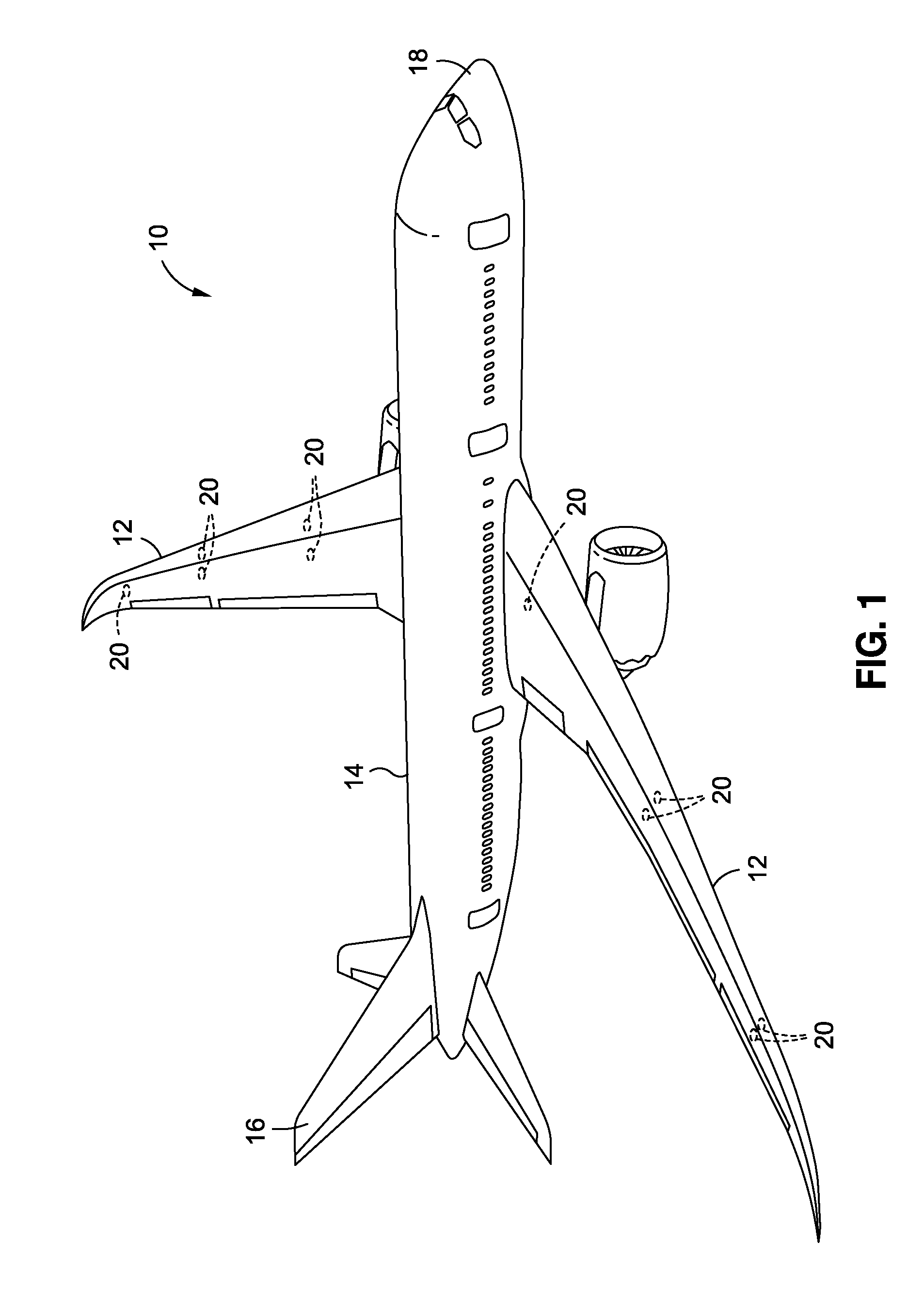
[0056]FIG. 1 is an illustration of a perspective view of an aircraft 10 which may incorporate one or more advantageous embodiments of a vent dam 20 of the disclosure. The aircraft 10 may be made from composite and / or metallic parts that may be used on portions of the aircraft 10, including but not limited to, wings 12, a fuselage 14, a tail 16, and a nose 18. One or more vent dams 20 may be positioned on one or both wings 12. Although the vent dam 20 is shown in an exemplary embodiment as used in an aircra...


PUM

PropertyMeasurementUnit
degree anglesaaaaaaaaaa
angleaaaaaaaaaa
angleaaaaaaaaaa

Abstract

The disclosure provides in one embodiment for a vent dam for use in a vent stringer in a fuel vent system. The vent dam comprises a contoured guiding surface for guiding fluid flow in a vent stringer. The vent dam further comprises one or more side flanges extending from the contoured guiding surface for providing attachment of the vent dam within the vent stringer.

Description

CROSS-REFERENCE TO RELATED APPLICATIONS[0001]The application is related to U.S. application Ser. No. 12 / 638,976, entitled “High PullOff Capability Hat Stringer”, filed on Dec. 15, 2009, and abandoned on Sep. 17, 2010, the entirety of which is incorporated by reference herein. The application is also related to U.S. application Ser. No. 12 / 474,005, entitled “Stringer Transition Method”, filed on May 28, 2009, and issued as U.S. Pat. No. 8,074,694 on Dec. 13, 2011, the entirety of which is incorporated by reference herein. The application is also related to U.S. application Ser. No. 12 / 332,093, entitled “Method for Producing Composite Laminates Using a Collapsible Mandrel”, filed on Dec. 10, 2008, and issued as U.S. Pat. No. 8,293,051 on Oct. 23, 2012, the entirety of which is incorporated by reference herein.BACKGROUND[0002]1) Field of the Disclosure[0003]The disclosure relates generally to fuel vent systems in aircraft and other craft, and more particularly, to a vent dam configurat...

Claims


Application Information

Patent Timeline
Patent Type & Authority Patents(United States)
IPC IPC(8): B64D37/02B64D37/04B64D37/32
CPCB64D37/32B64C3/182B64C3/34B64D37/06Y10T29/49622B64D37/005B64D37/10
Inventor BROOK, KENNETH L.KEEFE, BONNIE
Owner THE BOEING CO
Why Eureka
Try Eureka