Hybrid wind turbine blade bearing

a hybrid bearing and wind turbine technology, applied in the direction of elastic bearings, rigid support of bearings, machines/engines, etc., can solve the problem of very limited quick rotational movement of blades, and achieve the effect of increasing the ability to withstand high bending moments

Inactive Publication Date: 2015-04-21
AB SKF
View PDF8 Cites 13 Cited by
  • Summary
  • Abstract
  • Description
  • Claims
  • Application Information

AI Technical Summary

Benefits of technology

[0014]An object of the invention is therefore to provide an improved wind turbine blade pitch bearing device that is adapted for oscillating movements. A further object of the invention is to provide a wind turbine blade pitch bearing device that requires less maintenance. A further object of the invention is to provide a wind turbine blade pitch bearing device that is adapted to withstand an increased bending moment from the blade.
[0016]By this first embodiment of the bearing device according to the invention, a bearing device comprising two different bearing types is provided. This is advantageous in that one bearing type is optimized for small and quick oscillations and the other bearing type is optimized for larger and slower rotations. By optimizing the two bearing types for the different pitch oscillation cases of a wind turbine, the wear of the bearings can be reduced dramatically.
[0017]In a preferred embodiment, cylindrical elastomeric bearings are used for the small and quick pitch movements, i.e. oscillations, of a wind turbine blade. Several advantages are obtained. One advantage is that this type of bearing has a more or less unlimited life length since there is no wear induced on the bearing when used within its specifications. The bearing further does not require any maintenance. The bearing is stiff in the axial direction but will provide some damping since it comprises rubber. For a wind turbine blade, the quick rotational movements of the blade are very limited, normally up to 5 degrees, which resembles an oscillating movement. An elastomeric bearing is thus well suited for this type of movements.
[0019]In a further development of the invention, two spaced-apart bearing units are used, which increases the ability to withstand high bending moments on the blade. Further, the design of the bearing device makes it possible to reach the bearing device from within the hub and blade, which means that the blade need not be dismounted during maintenance.

Problems solved by technology

For a wind turbine blade, the quick rotational movements of the blade are very limited, normally up to 5 degrees, which resembles an oscillating movement.

Method used


Image

  • Hybrid wind turbine blade bearing
  • Hybrid wind turbine blade bearing
  • Hybrid wind turbine blade bearing

Examples


Embodiment Construction

[0023]The embodiments of the invention with further developments described in the following are to be regarded only as examples and are in no way to limit the scope of the protection provided by the patent claims.

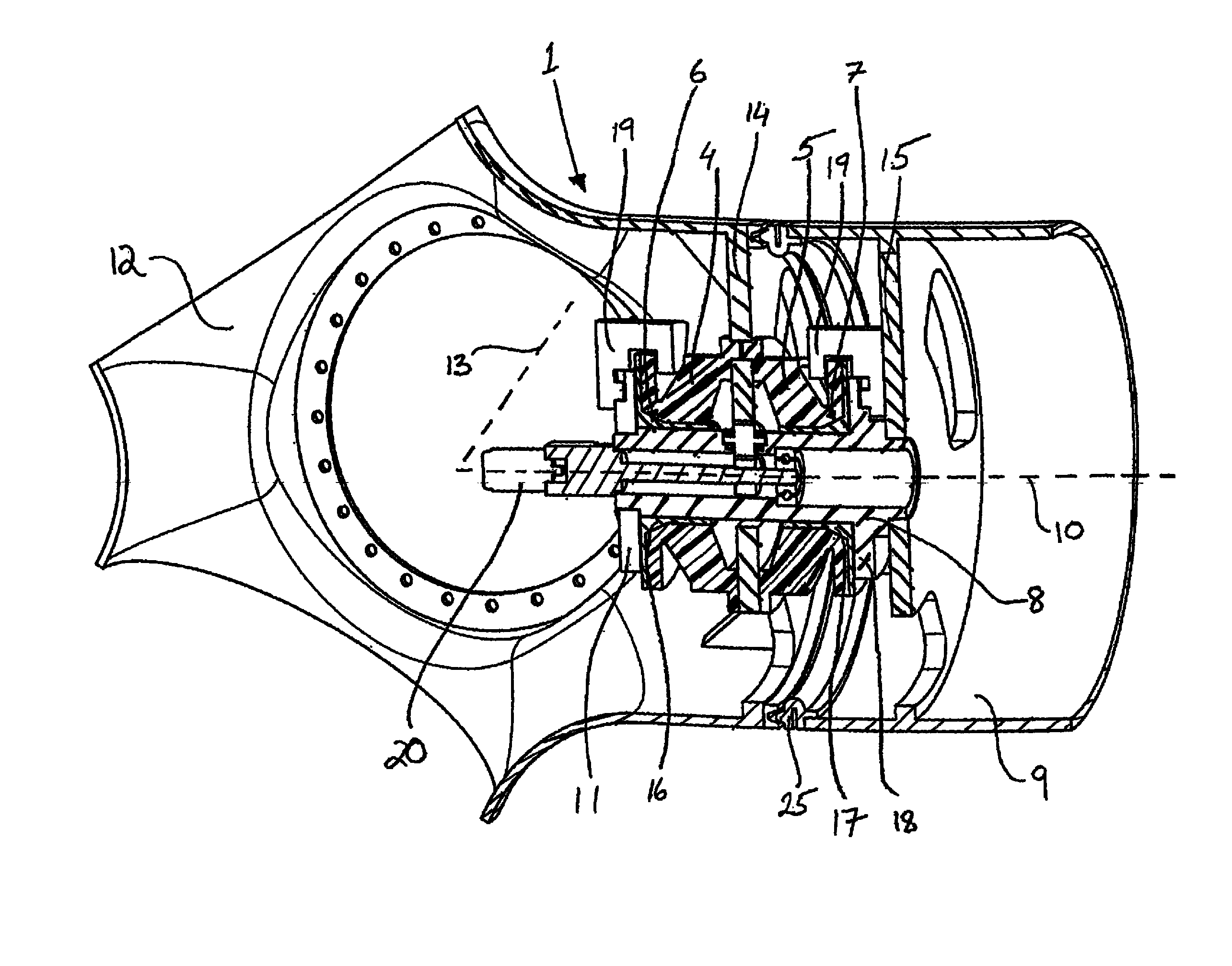
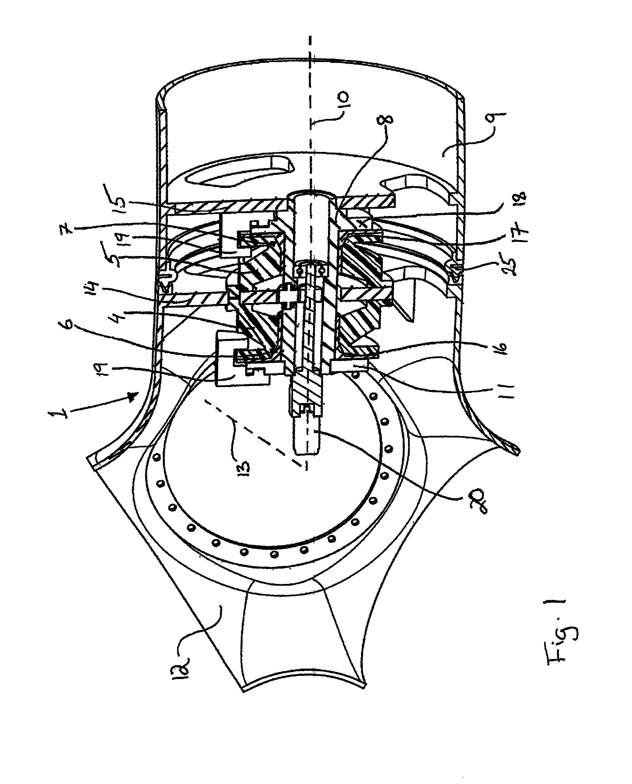
[0024]FIG. 1 shows a first embodiment of a wind turbine blade pitch bearing device adapted for rotational support of a turbine blade. In the figure, the wind turbine hub is shown from the front of the wind turbine, with the main shaft axis 13 perpendicular to a rotational axis 10 of the bearing device. The generator of the wind turbine is centred on the main shaft axis. The rotor of the wind turbine will comprise the hub with, in the shown embodiment, three blades attached to it. In FIG. 1, the hub 12 is shown with (part of) one blade 9 attached.

[0025]On a conventional hub, a regular roller bearing is mounted to the hub close to the hub centre. The outer ring of the bearing is mounted to the hub with many bolts, typically 50 to 80 bolts, which are pre-tensioned according to...


PUM


Abstract

Wind turbine blade pitch bearing device (1) adapted for rotational support of a turbine blade (9), having a first bearing unit (4, 5) and a second bearing unit (6, 7) coaxial to the first bearing unit. The first bearing unit (4, 5) and the second bearing unit (6, 7) are of different bearing types. By using two different bearing types, one bearing can be optimized for small and quick rotations and the other type can be optimized for larger and slower rotations.

Description

CROSS-REFERENCE[0001]This application is the U.S. national stage of International Application No. PCT / EP2011 / 000526 filed on Feb. 4, 2011, which claims priority to International Application No. PCT / EP2010 / 000727 filed on Feb. 5, 2010, both of which are herein incorporated by reference.TECHNICAL FIELD[0002]The present invention relates to a bearing device adapted to be used for the pitch adjustment of a wind turbine blade.BACKGROUND ART[0003]Wind turbines are designed to convert wind into electricity, by turning a generator positioned in a wind turbine housing, also known as a nacelle. The rotation of the generator is achieved by wind turbine blades, normally three, that rotate by the wind. In order to be able to optimize the output power of the wind turbine, the blades may be rotated around their longitudinal axis. In this way, the blades can be used to control the amount of wind power transferred from the wind to the generator.[0004]Normally, especially larger wind turbines are des...

Claims


Application Information

Patent Timeline
Patent Type & Authority Patents(United States)
IPC IPC(8): F16C27/06F03D7/02F03D11/00
CPCF03D11/0008F03D7/0224F03D7/0248F16C27/063F05B2240/54Y02E10/723Y02E10/722F16C2360/31F03D80/70Y02E10/72
Inventor MUELLER, THOMAS G.REEDMAN, ADAM V. C.BRUBAKER, ERIC L.
Owner AB SKF
Why Eureka
Try Eureka