
Power system for high temperature applications with rechargeable energy storage

a high temperature environment, power system technology, applied in secondary cells, servicing/maintenance of batteries, borehole/well accessories, etc., can solve the problems of increasing power demand of users, and increasing complexity of instrumentation

Active Publication Date: 2015-04-21
FASTCAP SYST
View PDF121 Cites 46 Cited by
  • Summary
  • Abstract
  • Description
  • Claims
  • Application Information

AI Technical Summary

Benefits of technology

The patent text describes a power system that can operate in high temperatures to provide power to a logging instrument downhole. The system includes a rechargeable energy storage that can store and release energy to power the instrument. The energy storage can provide power for multiple charge-discharge cycles and can be used to supplement the instrument's power needs. The system also includes a circuit that can control the energy storage's output and can manage performance. The technical effect of this system is to enable a reliable and efficient power supply for high-temperature environments, allowing for the continued operation of the logging instrument.

Problems solved by technology

As mankind continues to search for and extract oil, the quest for hydrocarbons has grown increasingly complex.
This complexity has given rise to all sorts of complicated instrumentation.
Consistent with other segments of technology, increasing complexity of instrumentation presents users with increasing power demands.
Unfortunately, the downhole environment presents real and unavoidable problems for system owners and operators.
The increased temperature can often present technical limitations when conventional power supplies fail.
For example, when chemically based battery storage is essentially degraded to the point of losing functionality.

Method used


Image

  • Power system for high temperature applications with rechargeable energy storage
  • Power system for high temperature applications with rechargeable energy storage
  • Power system for high temperature applications with rechargeable energy storage

Examples


Embodiment Construction

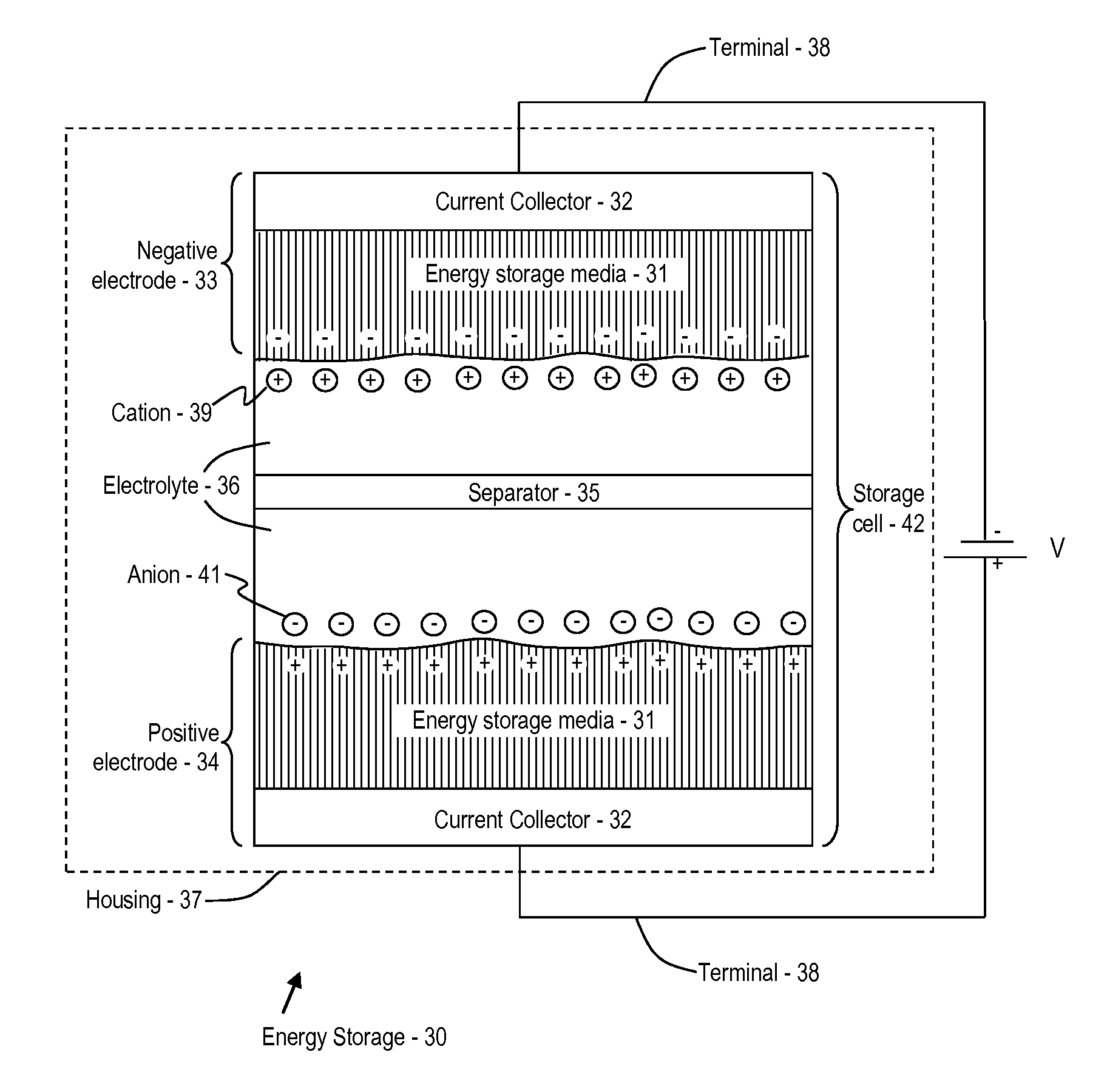
[0047]Disclosed herein is a power system that provides electrical energy in a high temperature environment. In addition to providing electrical energy in a high temperature environment, the power system may be configured to provide users with a variety of additional functions. While embodiments of the power system presented herein are configured for use in a downhole (i.e., subterranean) environment, it should be recognized that the power system may be used equally well in high temperature environments that present challenges to provision of reliable power. Such challenges may include environmentally harsh conditions, limited space available for containing energy storage, a substantially remote location where it is difficult to communicate with external power supplies and the like. Prior to introducing the power system in greater detail, some context is provided.

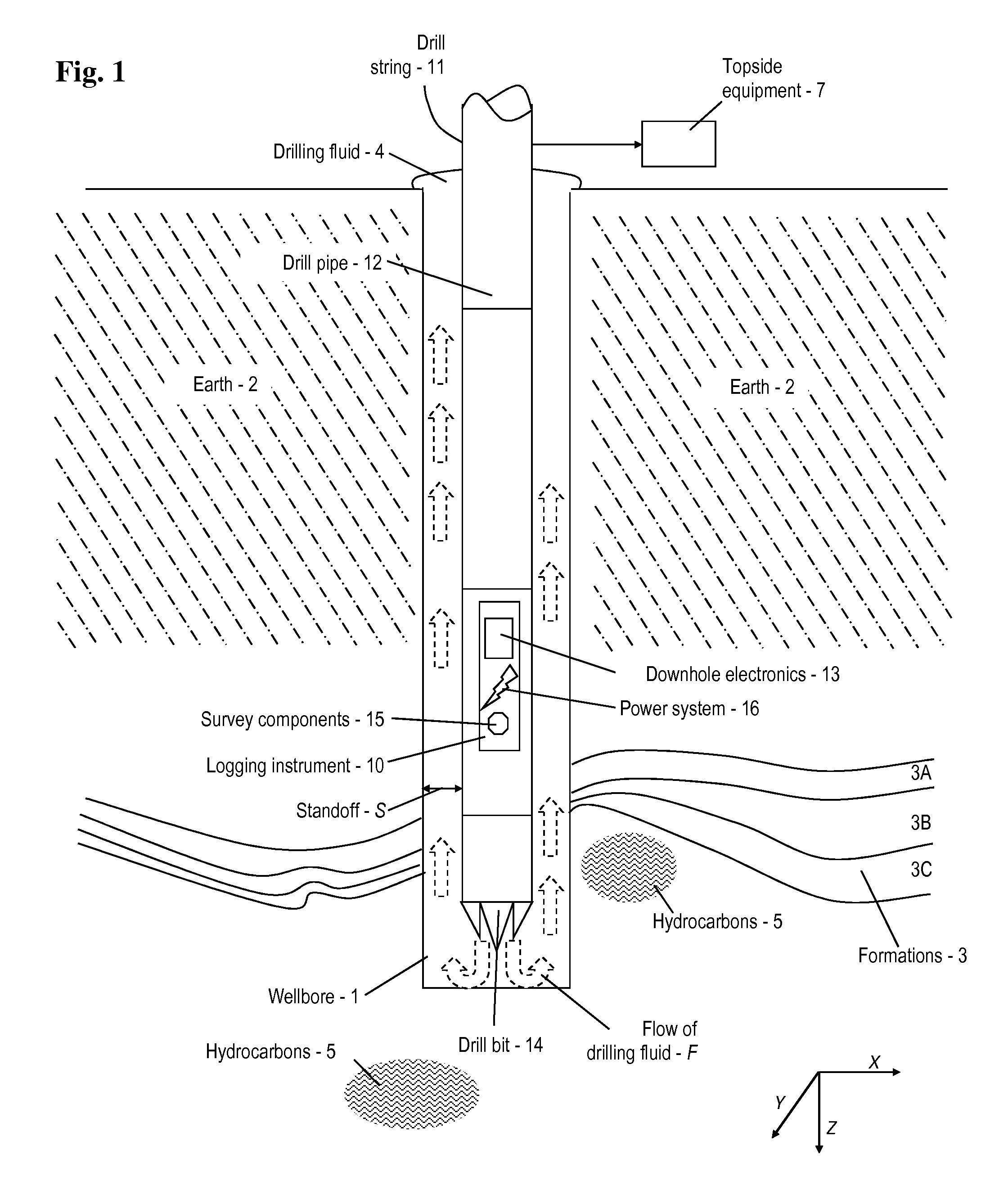
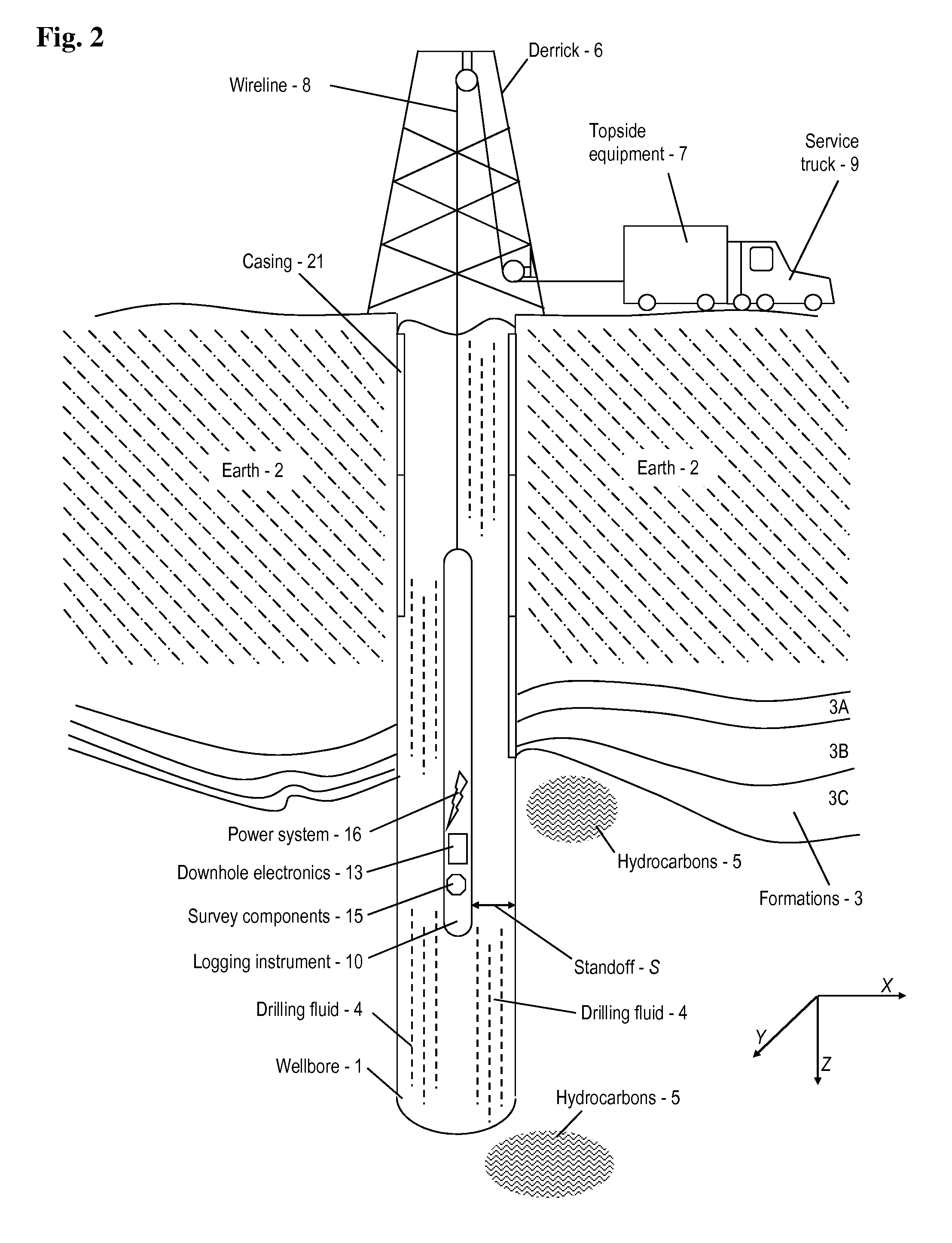
[0048]Refer now to FIG. 1 where aspects of an apparatus for drilling a wellbore 1 (also referred to as a “borehole”) are s...


PUM

PropertyMeasurementUnit
temperatureaaaaaaaaaa
peak poweraaaaaaaaaa

Abstract

A power system adapted for supplying power in a high temperature environment is disclosed. The power system includes a rechargeable energy storage that is operable in a temperature range of between about seventy degrees Celsius and about two hundred and fifty degrees Celsius coupled to a circuit for at least one of supplying power from the energy storage and charging the energy storage; wherein the energy storage is configured to store between about one one hundredth (0.01) of a joule and about one hundred megajoules of energy, and to provide peak power of between about one one hundredth (0.01) of a watt and about one hundred megawatts, for at least two charge-discharge cycles. Methods of use and fabrication are provided. Embodiments of additional features of the power supply are included.

Description

CROSS REFERENCE TO RELATED APPLICATIONS[0001]This application is filed under 35 U.S.C. §111(a) and claims priority under 35 U.S.C. §120 to U.S. patent application Ser. No. 12 / 928,896, entitled “Electrochemical Double Layer Capacitor for High Temperature,” filed Dec. 21, 2010; also claiming priority under 35 U.S.C. §119(e) to U.S. Provisional Patent Application Nos. 61 / 489,389 filed May 24, 2011; 61 / 493,039 filed Jun. 3, 2011; 61 / 494,332 filed Jun. 7, 2011; 61 / 537,360 filed Sep. 21, 2011; and 61 / 620,364 filed Apr. 4, 2012, the entire disclosures of which are incorporated by reference herein in their entirety.BACKGROUND OF THE INVENTION[0002]1. Field of the Invention[0003]This invention relates to methods and apparatus for providing power in a high temperature environment, in particular, for instrumentation and tooling used in subsurface environments generally in the exploration for hydrocarbons.[0004]2. Description of the Related Art[0005]As mankind continues to search for and extrac...

Claims


Application Information

Patent Timeline
Patent Type & Authority Patents(United States)
IPC IPC(8): H02J7/00B82Y30/00E21B41/00H01G11/08H01G11/36H01G11/58H01G11/62H01M10/39H01M10/42H01M50/107
CPCH01M10/39H01G11/62H01M10/425H01G11/08E21B41/0085Y10T29/49108H01G11/58H01M2220/10B82Y30/00Y02E60/13H01G11/36H01M50/107H01M10/48Y10T29/49117H02J7/0068H02J7/0071H01G2/065H01G11/10H01G11/14H01G11/32H01G11/60H01G11/78H01M10/4257H01M10/44H01M10/46H01M16/00H01M2010/4271H01M2010/4278H02J7/0042H02J7/345
Inventor COOLEY, JOHNSIGNORELLI, RICCARDOGREEN, MORRISKUTTIPILLAI, PADMANABAN SASTHANDEANE, CHRISTOPHERWILHELMUS, LINDSAY A.
Owner FASTCAP SYST
Learn More