
Clay mixing apparatus

a mixing apparatus and clay technology, applied in the field of clay mixing apparatus, can solve the problems of cracking or breaking in the firing step of biscuits, the size of the clay mixing apparatus grows larger, and it is difficult to readily remove the clay infiltrating the vacuum chamber, so as to reduce the distortion of the ejected clay

Active Publication Date: 2015-04-28
NIDEC SHIMPO CORP
View PDF18 Cites 2 Cited by
  • Summary
  • Abstract
  • Description
  • Claims
  • Application Information

AI Technical Summary

Benefits of technology

[0009]It is required for a clay mixing apparatus to readily discharge an air from a mixing chamber. It is also required for a clay mixing apparatus to efficiently remove the air contained in the clay during a kneading process. It is further required for a clay mixing apparatus to suppress distortion of the clay during an extruding process.
[0011]With such configuration, it is possible to easily reduce the internal pressure of the mixing chamber.
[0013]With such configuration, it is possible to efficiently remove the air contained in the clay during a mixing process.
[0015]With such configuration, it is possible to restrain distortion of the ejected clay.

Problems solved by technology

If an air remains within the clay for the manufacture of earthenware, crack or breakage may occur in a biscuit firing step.
In this structure, however, the size of the clay mixing apparatus grows larger.
In addition, it is impossible to readily remove the clay infiltrating into the vacuum chamber.
This makes it impossible to rapidly remove an air from the clay.

Method used


Image

  • Clay mixing apparatus
  • Clay mixing apparatus
  • Clay mixing apparatus

Examples


Embodiment Construction

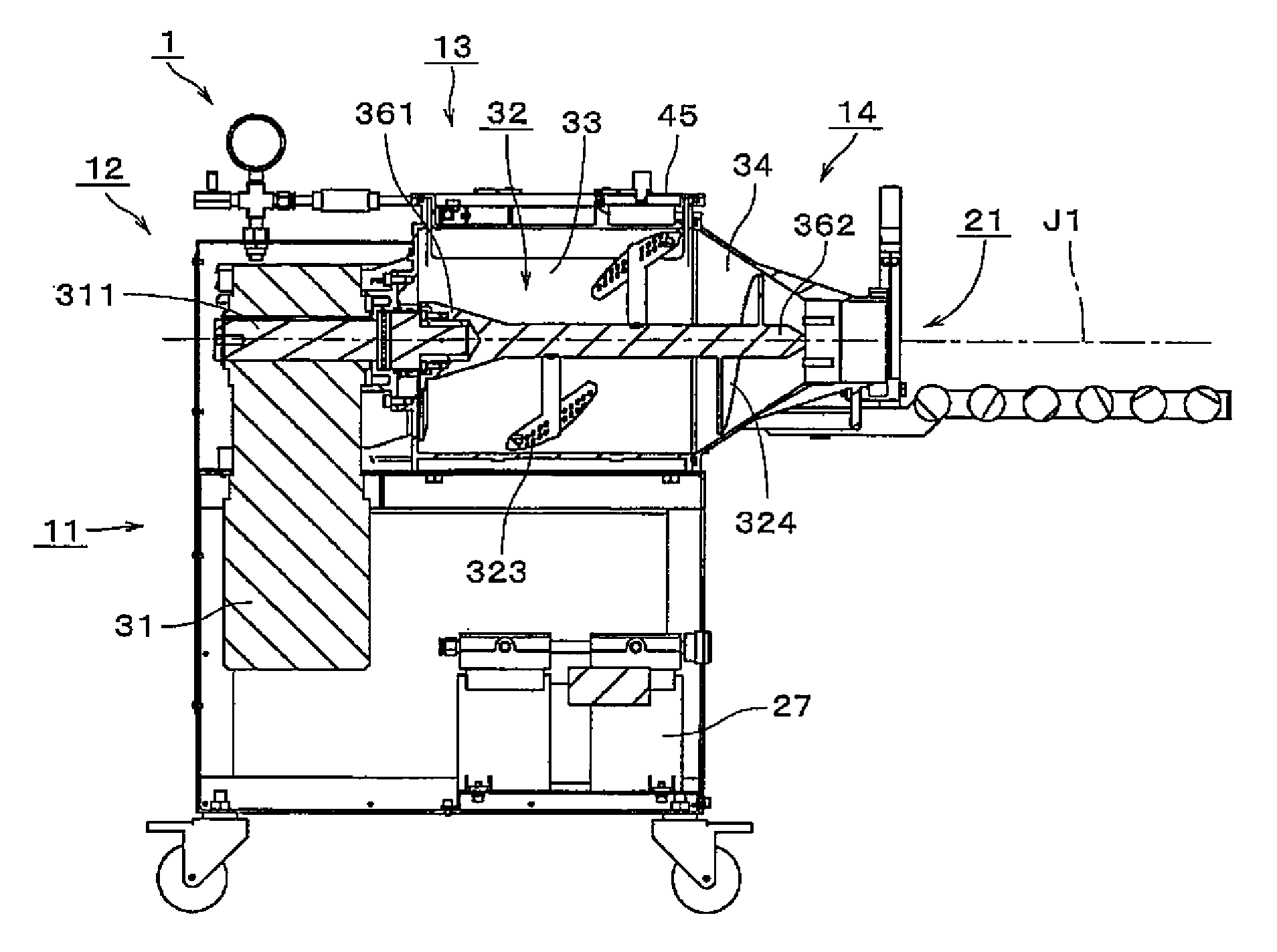
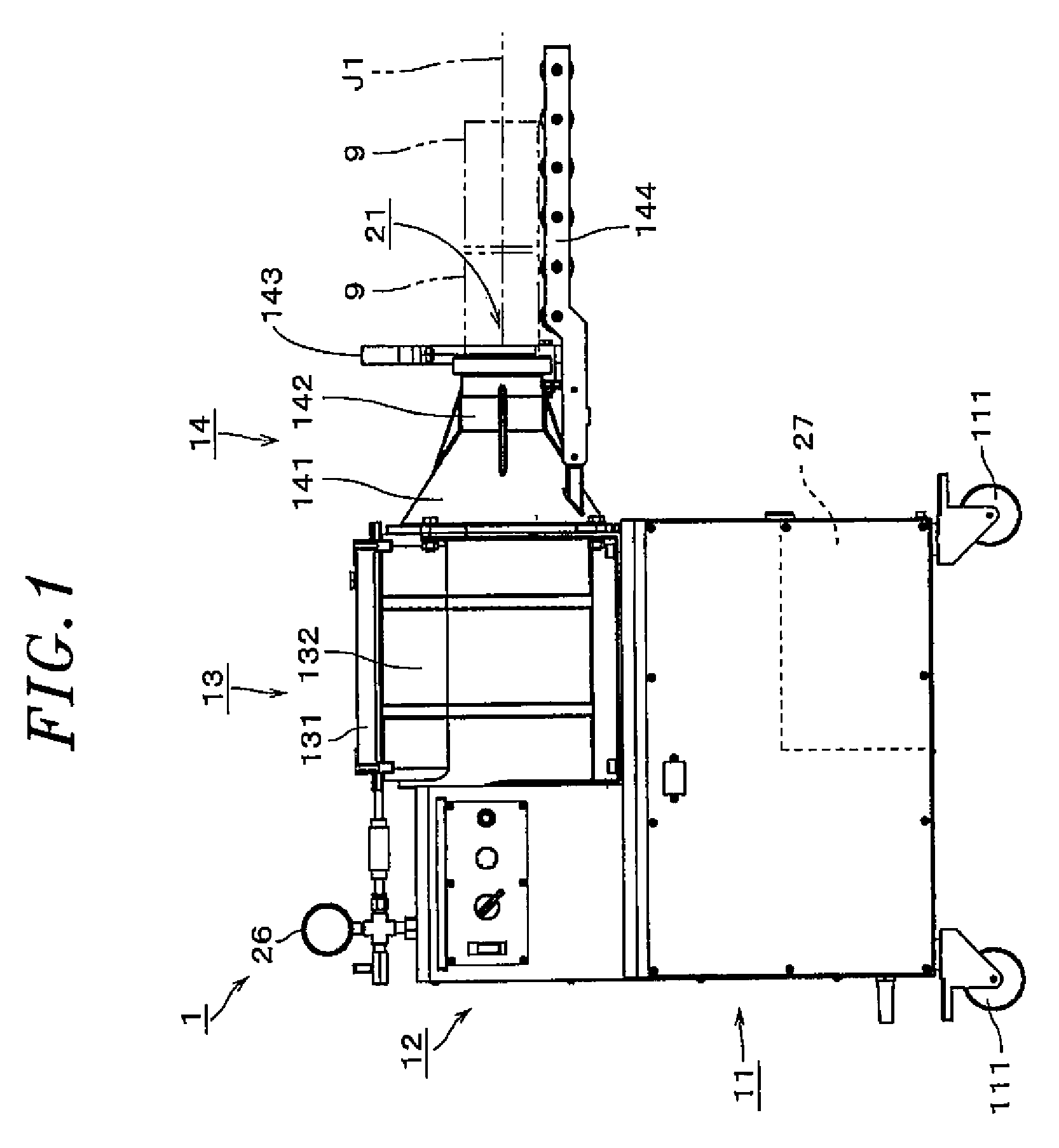
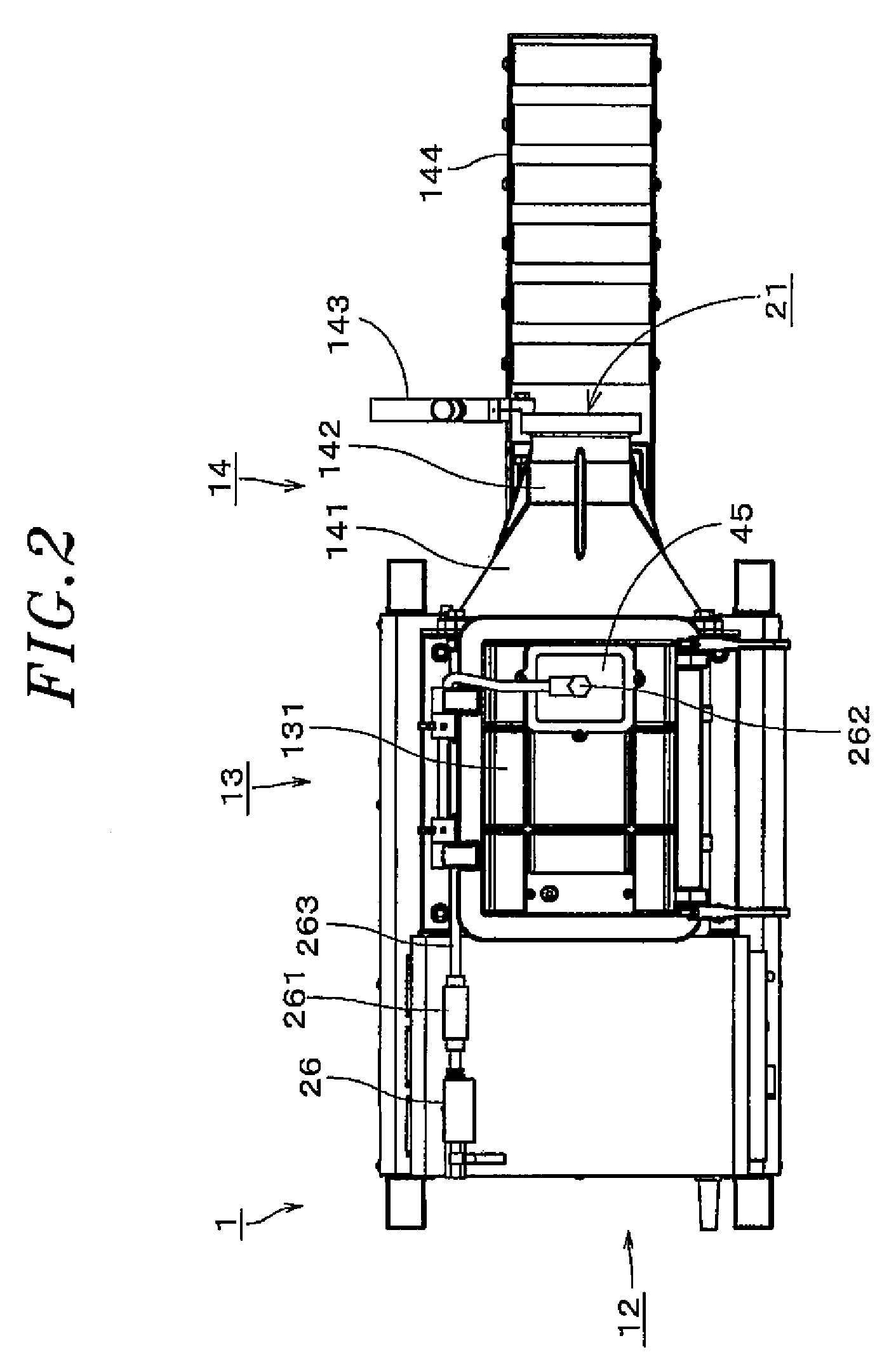
[0031]FIG. 1 is a front view showing a clay mixing apparatus 1 according to an illustrative embodiment of the present invention. FIG. 2 is a plan view of the clay mixing apparatus. FIG. 3 is a left side view of the clay mixing apparatus. FIG. 4 is a perspective view of the clay mixing apparatus. FIG. 5 is a perspective view of the clay mixing apparatus with a body lid kept opened.

[0032]The clay mixing apparatus 1 preferably includes a base 11, an operation unit 12, a mixing chamber 13 and an ejecting unit 14. The base 11 has a box-like shape and accommodates therein mechanisms and electric circuits which are needed to operate the clay mixing apparatus 1. Casters 111 are attached to the lower portion of the base 11. This makes it possible to easily move the clay mixing apparatus 1. The operation unit 12 preferably includes a power switch, a rotation direction, a rotation speed dial and so forth. As will be set forth later, a rotor rotating about a horizontal axis is provided within t...


PUM

PropertyMeasurementUnit
atmospheric pressureaaaaaaaaaa

Abstract

A clay mixing apparatus includes a mixing chamber, a rotor arranged within the mixing chamber, a drive unit arranged to rotate the rotor, an ejecting unit, a pressure reducing unit; and an exhaust flow path. The rotor includes a shaft rotated by the drive unit, an extruding member and a mixing member. The mixing member includes a plurality of arms and a plurality of blades arranged at tip ends of the arms. The exhaust opening is opposed, in a radial direction about the center axis, to a portion of the mixing member lying near the extruding member and / or a portion of the extruding member lying near the mixing member.

Description

BACKGROUND OF THE INVENTION[0001]1. Field of the Invention[0002]The present invention relates to a clay mixing apparatus for mixing clay.[0003]2. Description of the Related Art[0004]Conventionally, there has been used a clay mixing apparatus suitable for mixing clay to manufacture a piece of earthenware. If an air remains within the clay for the manufacture of earthenware, crack or breakage may occur in a biscuit firing step. In light of this, a variety of studies has been made in the field of clay mixing apparatus. For example, Japanese Patent Application Publication No. H7-214537 discloses a clay mixing apparatus in which an air is discharged from a mixing chamber by virtue of a vacuum suction device. Referring to FIG. 6 of Japanese Patent Application Publication No. H7-214537, a suction pipe is arranged at the rear side of the top of a lid in order to efficiently circulate the clay.[0005]U.S. Pat. No. 5,716,130 discloses a clay mixing apparatus in which a vacuum chamber is connec...

Claims


Application Information

Patent Timeline
Patent Type & Authority Patents(United States)
IPC IPC(8): B28C1/16B01F7/00B01F7/04B01F13/06B01F15/02B28B3/22B28C1/22B28C5/14
CPCB28C1/16B01F7/00133B01F7/00158B01F13/06B01F15/0289B28B3/222B28C1/225B28C5/143B01F7/003B01F7/00708B01F7/04B01F27/0723B01F27/0726B01F27/11251B01F27/2123B01F27/70B01F33/70B01F35/754551
Inventor KURIKI, MOTOKITOKUDA, TAKEOHIGASHITSUJI, MASAYA
Owner NIDEC SHIMPO CORP
Learn More