

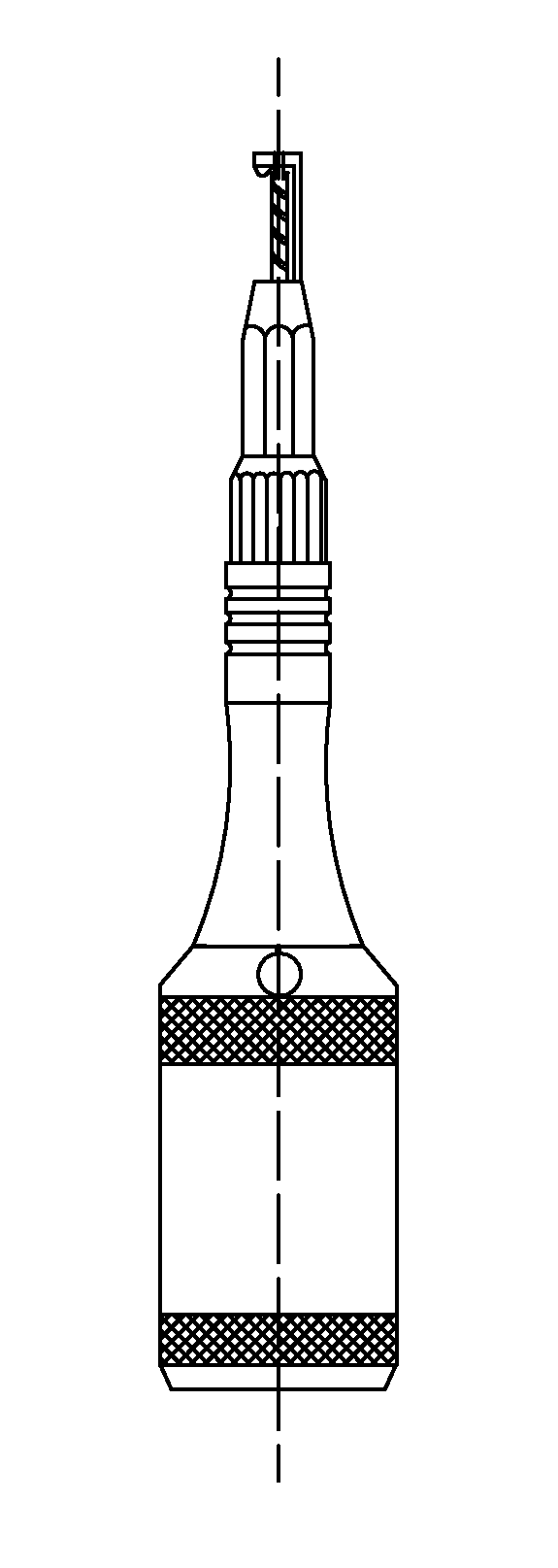
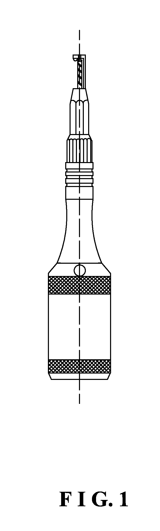
Surgical milling cutter
a milling cutter and cutter head technology, applied in the field of surgical cutting machines, can solve the problems of difficult rotation of the milling cutter, inconvenient use, and the inability of the cylindrical head to work, so as to avoid uneven cutting of objects, facilitate operation, and reduce processing costs
- Summary
- Abstract
- Description
- Claims
- Application Information
AI Technical Summary
Benefits of technology
Problems solved by technology
Method used
Image

Examples
Embodiment Construction
[0038]Embodiments of the present invention will now be described, by way of example only, with reference to the accompanying drawings.
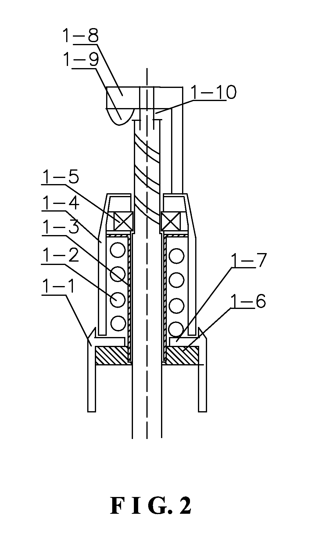
[0039]As shown in FIG. 1 to FIG. 9, a surgical milling cutter comprises a milling cutter holder, a locking device, a locking seat, and a main machine. The milling cutter holder comprises a fixing seat (1-1) with a through hole. A finger guider (1-4) with an L-type holder on a top end thereof is arranged at an upper part of the fixing seat (1-1). A distal end of a short side (1-8) of the L-type holder is provided with a downward projection (1-9), and a lowest point of the projection (1-9) is lower than that of a cylindrical head (1-10) when the milling cutter works normally. Thus, the projection (1-9) can prevent an object from contacting the cylindrical head, thereby avoiding occurrence of the phenomenon of unevenly cutting the object. A T-shaped bolt (1-3) with a central through hole is fixed in a cavity of the finger guider (1-4). A pressing disk (1...
PUM
 Abstract
Description
Claims
Application Information