Fastener and material remover
a fastener and material technology, applied in metal-working equipment, portable percussive tools, metal-working equipment, etc., can solve the problems of labor-intensive and difficult removal of old materials and fasteners, and achieve the effect of efficient removal of fasteners and materials, convenient and convenient manner, and no unnecessary effor
- Summary
- Abstract
- Description
- Claims
- Application Information
AI Technical Summary
Benefits of technology
Problems solved by technology
Method used
Image
Examples
first embodiment
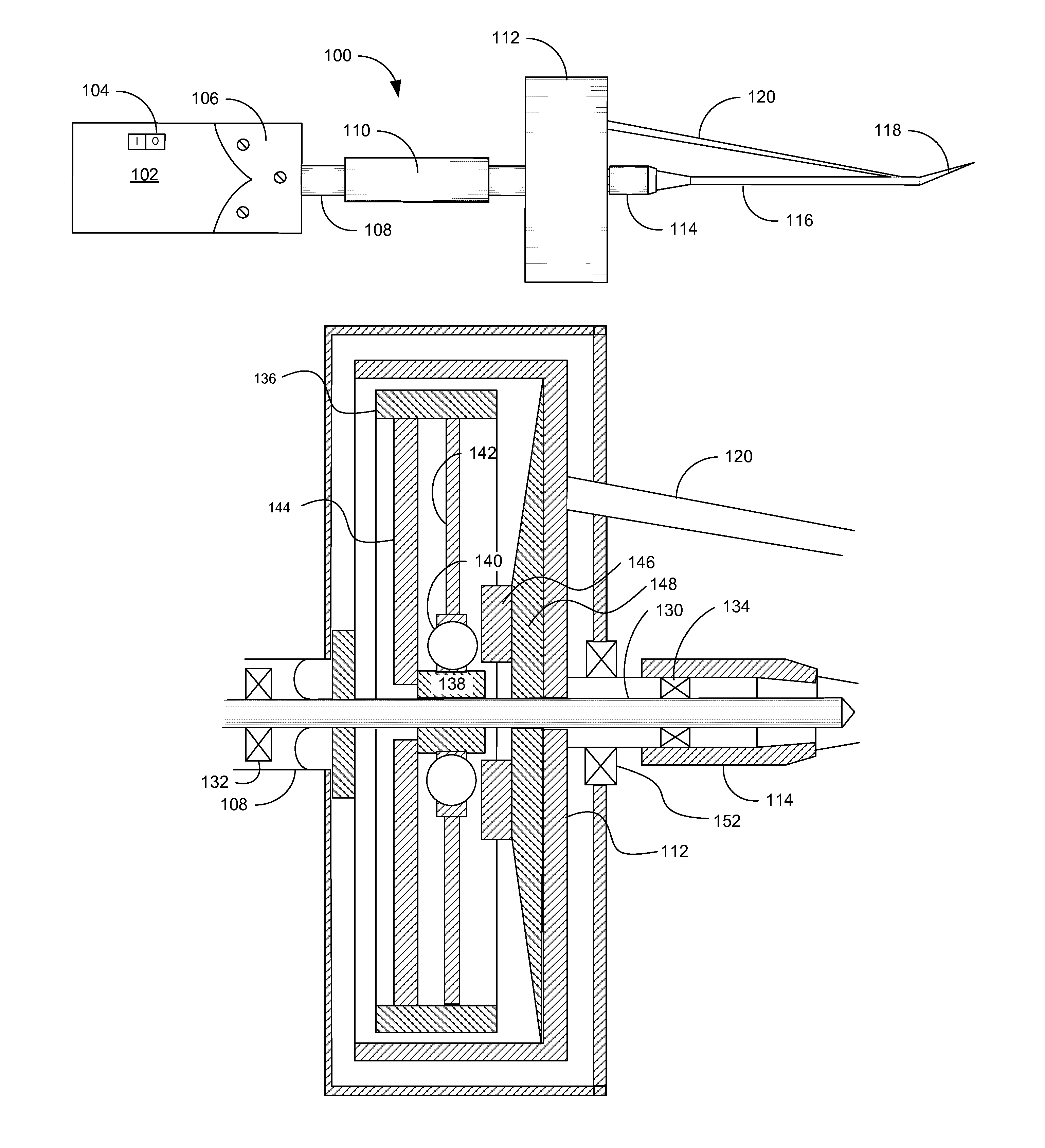
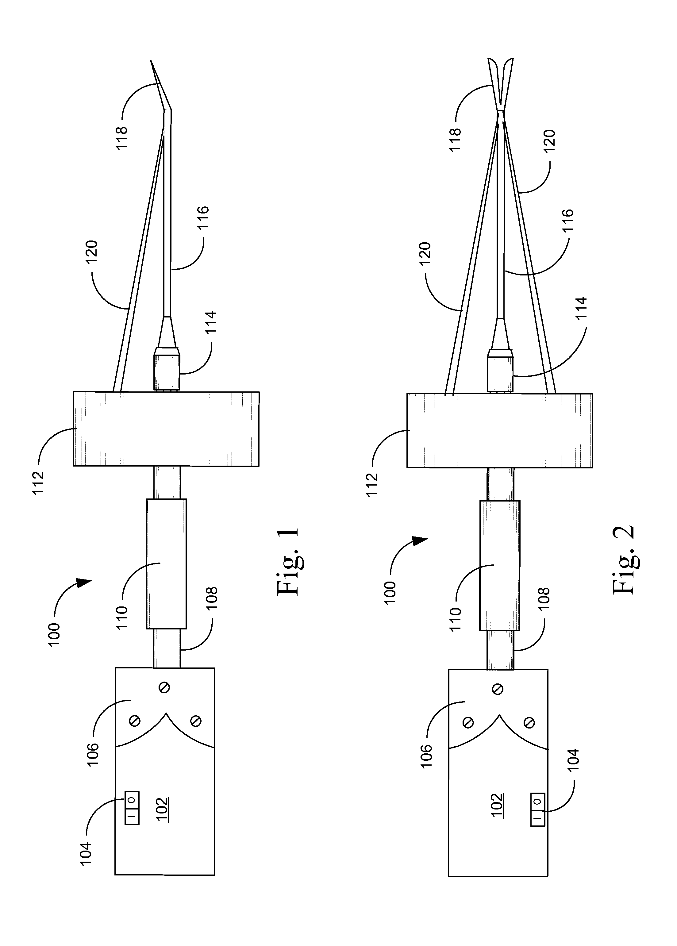
[0017]Referring now to FIGS. 1 and 2, the present disclosure is described in greater detail in reference to one general embodiment of the fastener removal apparatus according to the present disclosure. FIG. 1 depicts a side view of a fastener removal apparatus in accordance with the disclosure. FIG. 2 is a top view of the fastener removal apparatus depicted in FIG. 1. As seen in FIGS. 1 and 2, apparatus 100 comprises motor 102 having switch 104 and connected to handle 108 by bracket 106. Handle 108 has a grip 110 to facilitate secure engagement. Canister 112 is secured to handle 108 on one end and strike shaft 116 on the other via coupling 114. At the end of strike shaft 116 is a shear blade 118. Strike shaft 116 is supported by a set of braces 120.
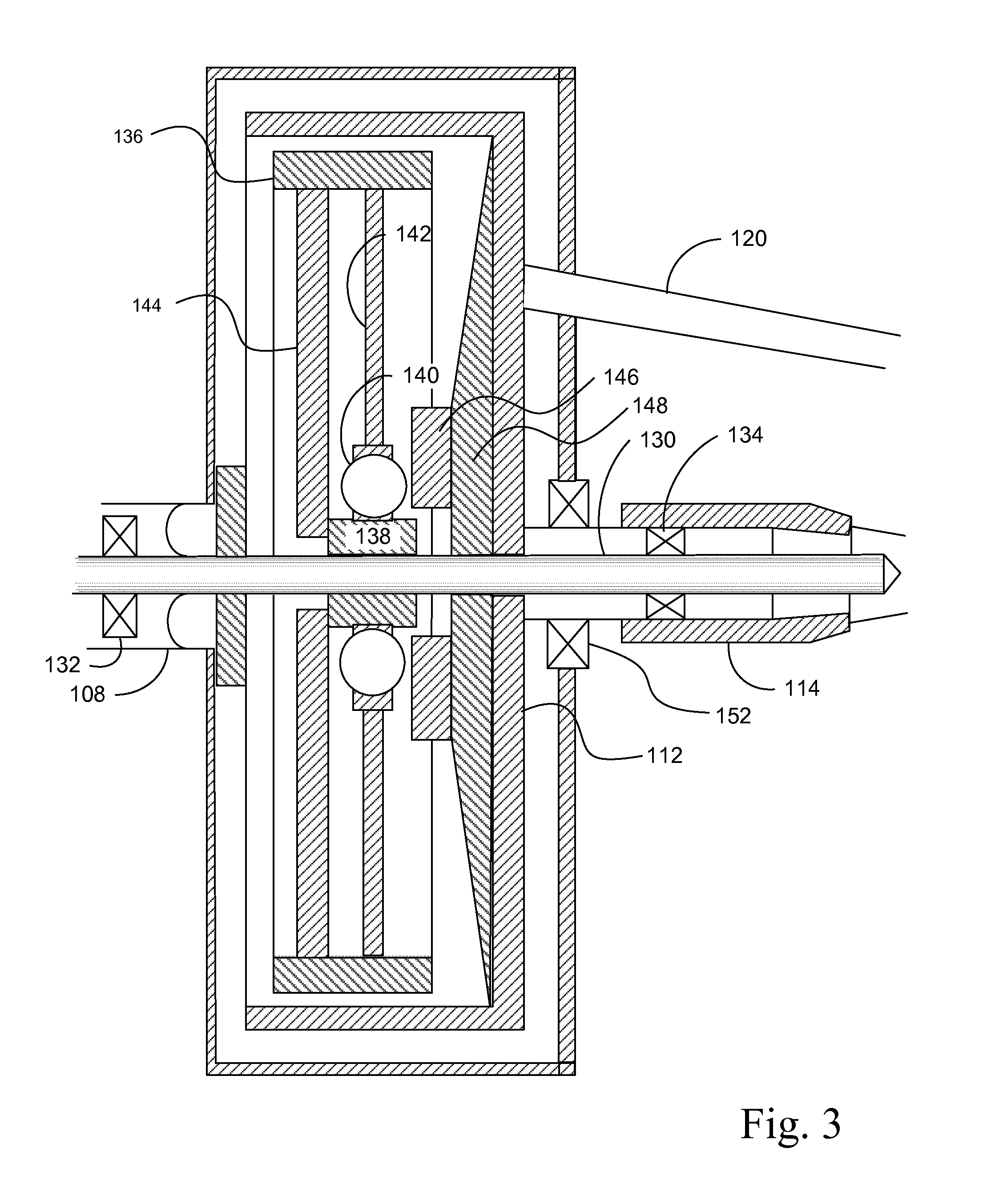
[0018]FIG. 3 is a side section view of the fastener removal apparatus shown in FIGS. 1 and 2. As seen in FIG. 3, drive shaft 130 rides on bearings 132, 134. Drive shaft 130 is operably connected to moter 102 in such manner as to be rotata...
second embodiment
[0022]FIG. 4 is a top section view of the fastener removal apparatus of the present invention. FIG. 5 is a front section view of the fastener removal apparatus of FIG. 4. Apparatus 200 comprises a motor 202 secured to an upper frame 204 having a pair of upper handholds 206. A pair of pilot pins 208 extend from the upper frame 204 to lower frame 210. A pair of retention springs 214 provide for movement between upper frame 206 and lower frame 210. A pair of lower handholds 212 are secured to lower frame 210. A lubrication retaining fence 216, having an air filter 218 secured thereto, is secured to lower frame 210.
[0023]A drive pulley 220, secured to the output shaft of motor 202, powers a driven pulley 222, disposed about internal pilot pin 226, via a drive belt 224. Driven pulley 222 is, in turn, secured to primary flywheel 228, which is also disposed about internal pilot pin 226. A secondary flywheel 230, disposed about internal pilot pin 232, engages with, and is driven by, primary...
PUM
| Property | Measurement | Unit |
|---|---|---|
| volume | aaaaa | aaaaa |
| compositions | aaaaa | aaaaa |
Abstract
Description
Claims
Application Information
 - R&D
- Intellectual Property
- Life Sciences
- Materials
- Tech Scout
- Unparalleled Data Quality
- Higher Quality Content
- 60% Fewer Hallucinations
Browse by: Latest US Patents, China's latest patents, Technical Efficacy Thesaurus, Application Domain, Technology Topic, Popular Technical Reports.
© 2025 PatSnap. All rights reserved.Legal|Privacy policy|Modern Slavery Act Transparency Statement|Sitemap|About US| Contact US: help@patsnap.com


