
Wear indicators for drilling equipment

a technology for drilling equipment and wear indicators, which is applied in the direction of earth drilling tools, earth drilling and mining, drilling accessories, etc., can solve the problems of difficult to obtain a wear assessment for drill bits, inability to determine the original blade height of impregnated bits, and inability to determine the amount of wear. the effect of accuracy

Inactive Publication Date: 2015-05-05
HALLIBURTON ENERGY SERVICES INC
View PDF7 Cites 8 Cited by
  • Summary
  • Abstract
  • Description
  • Claims
  • Application Information

AI Technical Summary

Benefits of technology

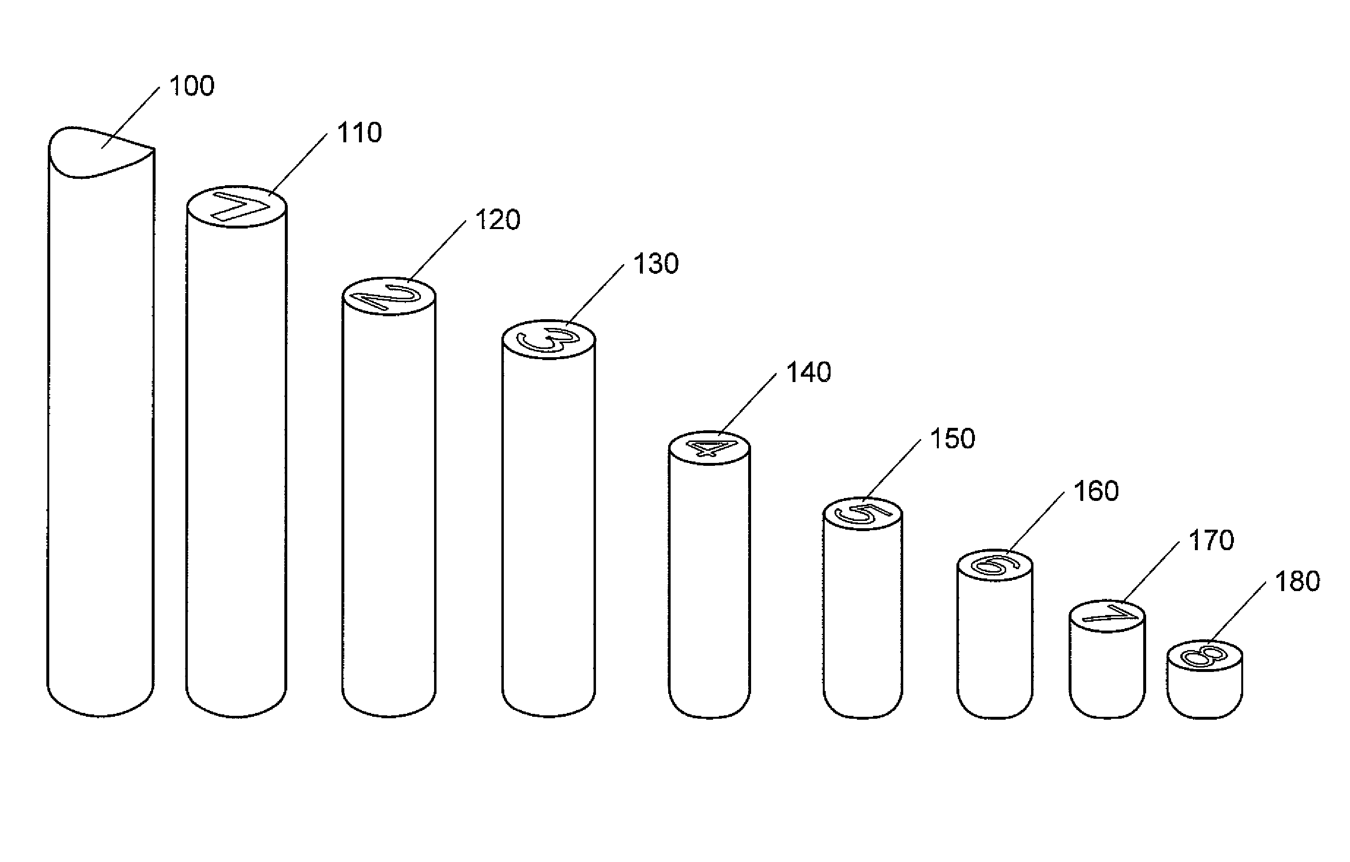
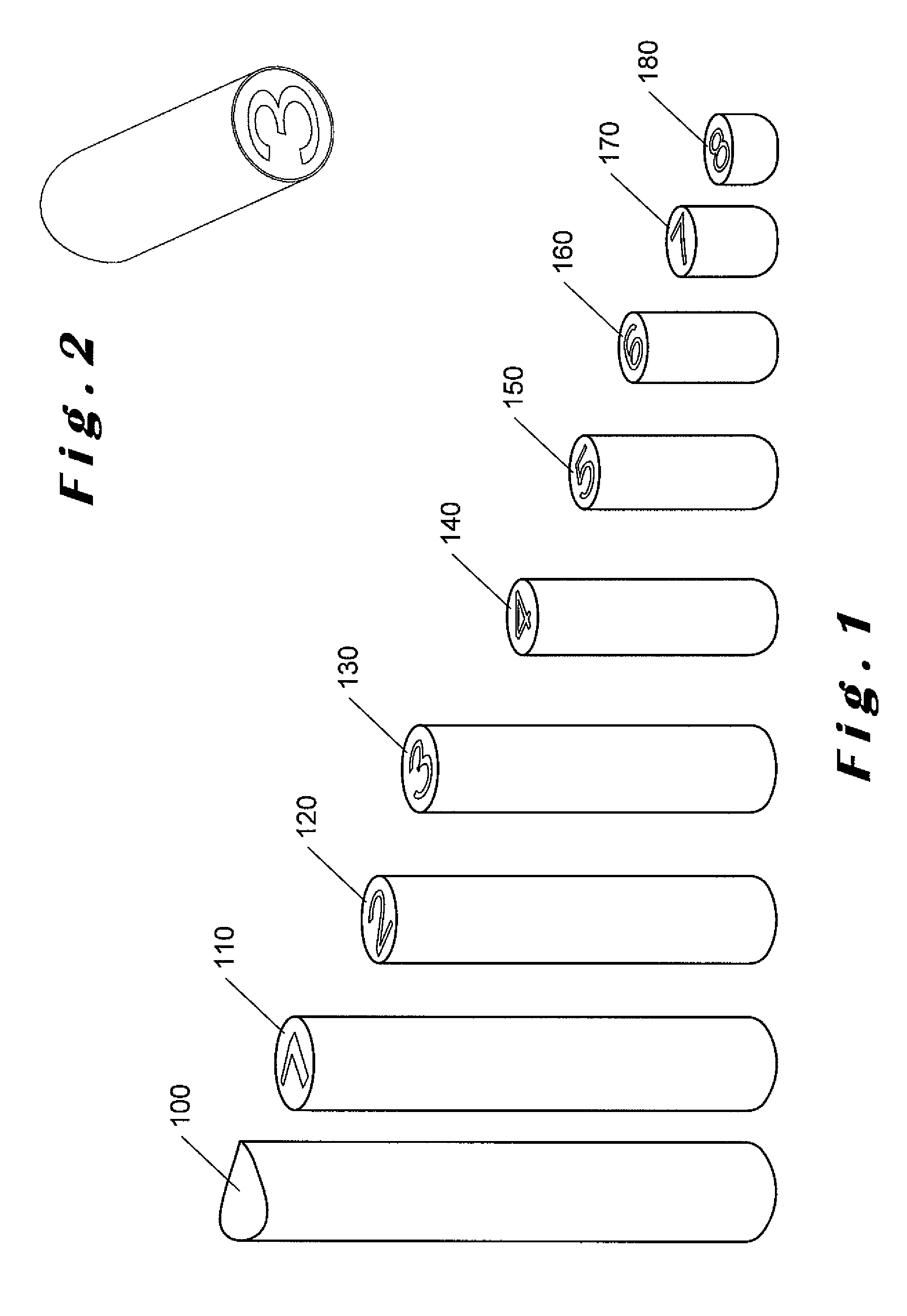
[0012]By having regions with numbers formed in them, an indication of wear can be readily determined without the need to make any measurements.
[0015]Ideally, the elongate element may comprise a closed end that is indicative of no wear. This means that an unworn drill bit can easily be identified. Alternatively, the elongate element may comprise an open end having the number “0” formed therein that is indicative of no wear.

Problems solved by technology

However, it can be difficult to obtain a wear assessment for drill bits, in general, in terms of a wear level at stages of operation.
However, as the determination of wear depends on a measurement, it can be inconsistent and therefore unreliable, particularly as when worn, it is impossible to determine the original blade height for impregnated bits.
However, the wear indicator described in U.S. Pat. No. 6,167,833 suffers from the disadvantage that, unless one is familiar with the particular wear indicator and how it progresses during the lifetime of the tool in which it is embedded, the determination of the amount of wear may be less than accurate.

Method used


Image

  • Wear indicators for drilling equipment
  • Wear indicators for drilling equipment
  • Wear indicators for drilling equipment

Examples


Embodiment Construction

[0033]The present invention will be described with respect to particular embodiments and with reference to certain drawings but the invention is not limited thereto. The drawings described are only schematic and are non-limiting. In the drawings, the size of some of the elements may be exaggerated and not drawn on scale for illustrative purposes.

[0034]It will be understood that the terms “vertical” and “horizontal” are used herein refer to particular orientations of the Figures and these terms are not limitations to the specific embodiments described herein.

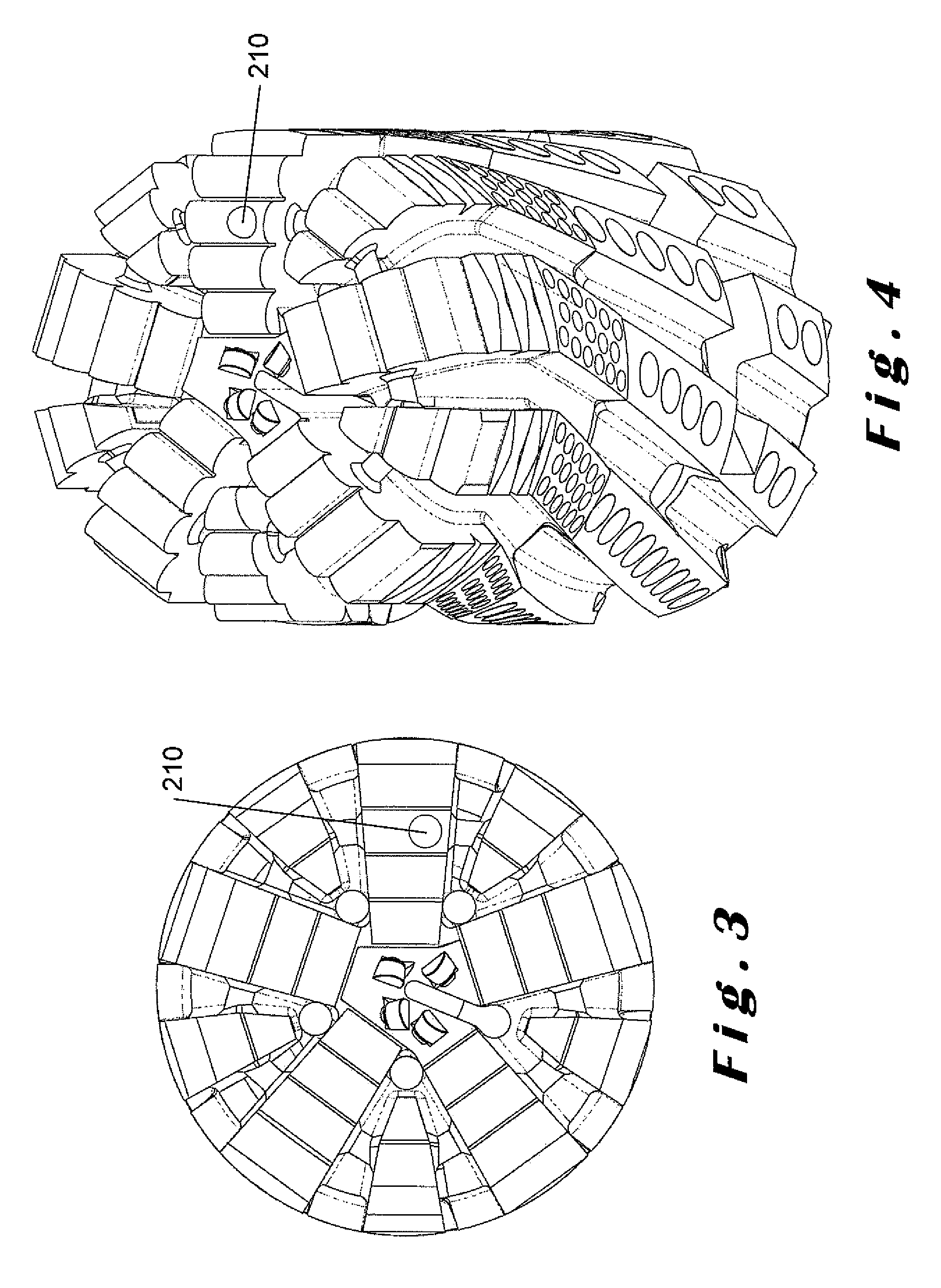
[0035]In a preferred embodiment of the present invention, a wear indicator is provided that comprises a series of numbers which indicate the level of wear of a drill bit and / or a core head. Each number is made as a void formed in the wear indicator. The numbers are still discernible even if the void forming the number is filled with cuttings from the drilling process. Ideally, these numbers correspond to respective wear levels in...


PUM


Abstract

Described herein is a wear indicator (100) for use in a drill bit or a core head. The wear indicator (100) comprises an elongate element that forms part of the drill bit. The elongate element has a plurality of numbers (110, 120, 130, 140, 150, 160, 170, 180) formed along its length, each number (110, 120, 130, 140, 150, 160, 170, 180) being formed as a void and corresponds to a level of wear in accordance with the IADC dull grading system. As the drill becomes worn, the wear indicator (100) wears at the same rate to reveal one of the numbers (110, 120, 130, 140, 150, 160, 170, 180). The numbers range from “1” to “8” where the number “1” illustrates the least wear and the number “8” indicates the most wear. When unworn, none of the numbers are visible.

Description

CROSS REFERENCE TO RELATED APPLICATIONS[0001]This application is a U.S. National Stage Application of International Application No. PCT / EP2011 / 059203 filed Jun. 3, 2011, which designates the United States, and which is incorporated herein by reference in its entirety.FIELD OF THE INVENTION[0002]The present invention relates to wear indicators for drilling equipment, and is more particularly, although not exclusively, concerned with wear indicators for drill bits having a fixed cutting structure and core heads used in drilling operations.BACKGROUND[0003]Two classes of drilling tools are used in oil drilling, namely, roller-cone bits and fixed-cutter bits. Roller-cone bits have moving parts whilst fixed-cutter bits are mono-block without any moving parts.[0004]Drill bits with fixed cutting structures fall into four sub-categories according to the nature of their cutters. Such cutters can be made of polycrystalline diamond compacts (PDC), natural diamonds, thermally stable polycrystall...

Claims


Application Information

Patent Timeline
Patent Type & Authority Patents(United States)
IPC IPC(8): E21B12/02
CPCE21B12/02
Inventor DUPONT, OLIVIERDA SILVA, NUNO
Owner HALLIBURTON ENERGY SERVICES INC
Learn More