Shield connector

a shield connector and connector technology, applied in the direction of coupling device connection, two-part coupling device, electrical apparatus, etc., can solve the problems of increasing the number of parts, inconvenience in assembly of shield connectors, and deteriorating high frequency performance of shield electric cables, so as to improve the high frequency performance of signals, and suppress the disorder of impedan

Inactive Publication Date: 2015-05-12
YAZAKI CORP
View PDF13 Cites 4 Cited by
  • Summary
  • Abstract
  • Description
  • Claims
  • Application Information

AI Technical Summary

Benefits of technology

[0011]It is an object of the present invention to provide a shield connector that can improve the high frequency performance by enabling adjusting of the impedance with the shield electric cable without additional parts.
[0015]According to the first aspect of the present invention, in the inner terminal, the impedance adjusting portion is provided between the electric connecting portion to be electrically connected with the mating terminal and the crimp barrel portion with which the end of the core wire is connected, so that the impedance of the entirety of the shield connector can be adjusted on the inner terminal side. This adjusting suppresses the disorder of the impedance, thus enabling to improve the high frequency performance of the signal transmitted by the shield electric cable. With the above structure, the inner terminal suppresses the disorder of the impedance, which dispenses with other additional parts for suppressing the disorder of the impedance and increase of the number of parts, thus facilitating assembling of the shield connector.
[0016]Further, when the inner terminal is to be received in the inner housing, the impedance adjusting portion of the inner terminal is mated with the mating groove portion of the inner housing. This enables to easily position the inner terminal to the inner housing as well as to reliably fix the inner terminal to the inner housing.
[0017]Further, forming the bottom plate portion and the side plate portions at the impedance adjusting portion brings about a structure allowing the impedance adjusting portion to reliably cover the core wire of the shield electric cable, thus enabling to easily suppress the disorder of the impedance. Further, the bottom plate portion of the impedance adjusting portion is continuous with the electric connecting portion and the crimp barrel portion, thus enabling to easily form the impedance adjusting portion at the inner terminal.

Problems solved by technology

In the open portion, impedance is locally enhanced to thereby disorder the impedance, thus leading to deterioration of the high frequency performance of the signal transmitted by the shield electric cable.
This causes such problems as to increase the number of parts as well as to inconvenience assembling of the shield connector.

Method used


Image

  • Shield connector
  • Shield connector
  • Shield connector

Examples


Embodiment Construction

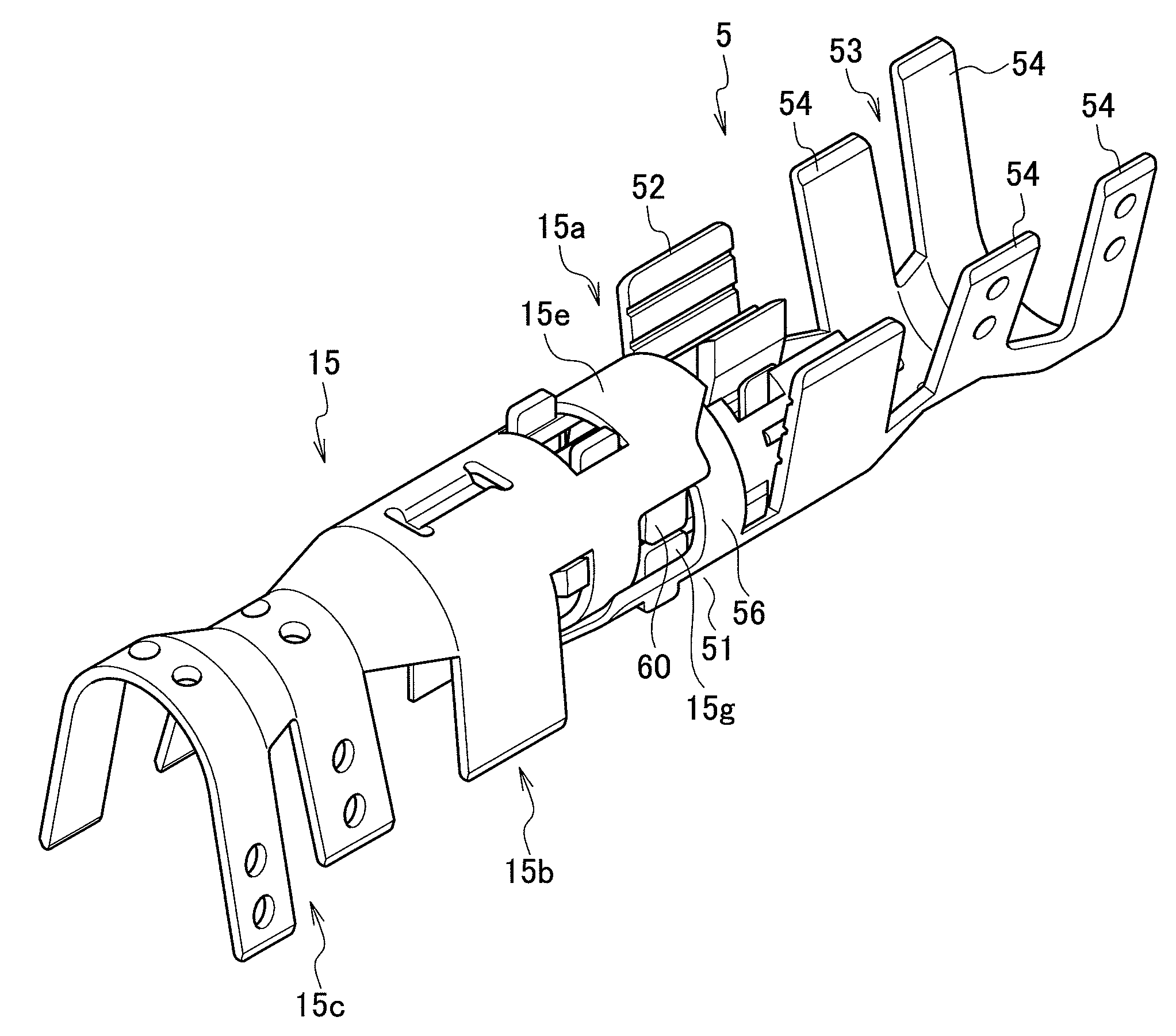
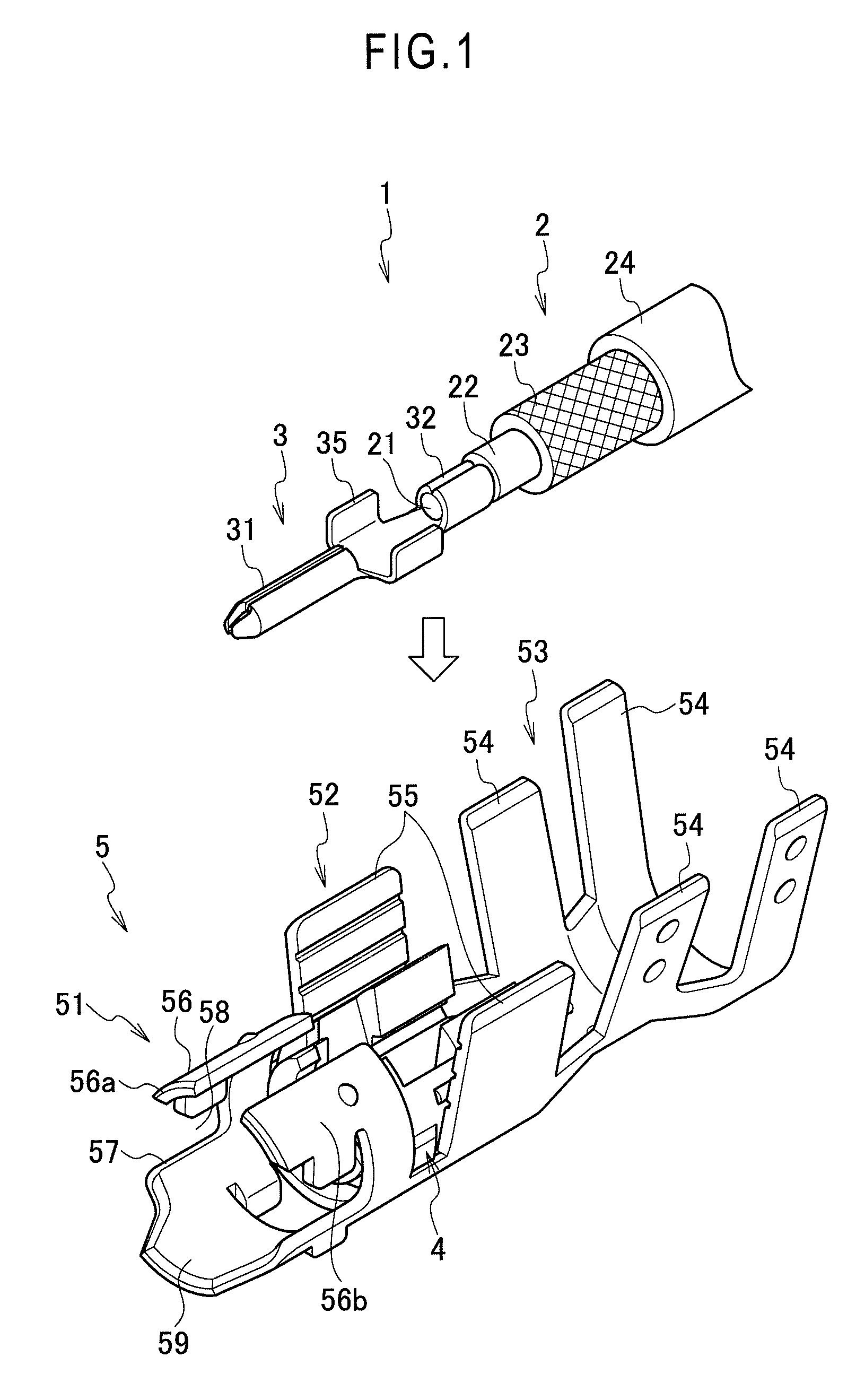
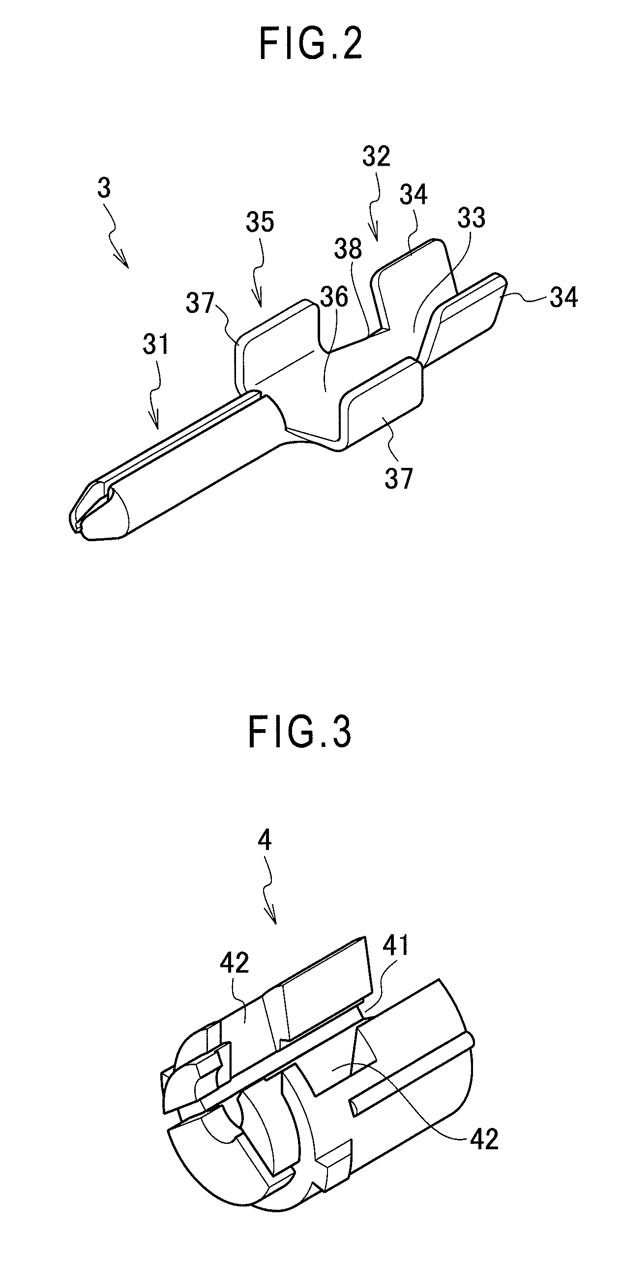
[0028]As shown in FIG. 1, a shield electric cable 2 is connected to a shield connector 1. As shown in FIG. 1 and FIG. 10, the shield electric cable 2 has a coaxial structure formed by: a central core wire 21 formed by twining together a plurality of conductive wires; an inner cover 22 made of an insulation resin and so provided as to cover an outer periphery of the core wire 21; a shield member 23 made of conductive braided wires and so provided as to cover an outer periphery of the inner cover 22; and an outer cover 24 made of an insulation resin and so provided as to cover an outer periphery of the shield member 23. Of these, the core wire 21 transmits a high frequency signal, and the shield member 23 shields an electromagnetic wave. With the shield member 23 exposed by peeling off the outer cover 24 and the core wire 21 exposed by peeling off the inner cover 22, the above shield electric cable 2 is used for connection with the shield connector 1.

[0029]As shown in FIG. 1 and FIG. ...


PUM


Abstract

An inner terminal is provided with a crimp barrel portion with which a terminal of a core wire is connected and an electric connecting portion to be electrically connected with a mating terminal. The inner terminal is received in an insulation inner housing. The inner housing is set into a terminal body portion. An outer terminal is provided with a shield member connecting portion with which a shield member is connected and a cylindrical portion in which the electric connecting portion of the inner terminal is positioned, the cylindrical portion mated with a mating connector. An impedance adjusting portion is provided between the electric connecting portion and the crimp barrel portion of the inner terminal.

Description

CROSS-REFERENCE TO RELATED APPLICATIONS[0001]This application claims the priority of Application No. JP 2011-289305 filed Dec. 28, 2011, in the Japanese Patent Office (JPO), the disclosures of which are incorporated herein in their entirety.BACKGROUND OF THE INVENTION[0002]1. Field of Invention[0003]The present invention relates to a shield connector capable of easily making an adjustment with impedance of a shield electric cable connected with the shield connector.[0004]2. Description of the Related Art[0005]A shield electric cable is used for transmitting a high frequency signal to a control board of an electric apparatus such as a vehicular television, radio, and navigation system. This shield electric cable is a coaxial cable formed by a core wire made by twining together a plurality of wires, a shield member made of braided wires which cover an outer periphery of the core wire via an inner cover made of insulation, and an outer cover made of insulation which covers an outer per...

Claims


Application Information

Patent Timeline
Patent Type & Authority Patents(United States)
IPC IPC(8): H01R9/03H01R13/6581H01R13/6474H01R24/44H01R9/05H01R13/213
CPCH01R13/6581H01R9/0518H01R13/213H01R13/6474H01R24/44
Inventor KANDA, HIDENORIMIYAWAKI, KOJI
Owner YAZAKI CORP
Why Eureka
Try Eureka