Organic electroluminescent device and transparent impedance line

a technology of electroluminescent devices and impedance lines, which is applied in the field of luminescent devices, can solve the problems of non-uniform luminance in the luminescent zone and the inability of the organic electroluminescent devices to be lighted, and achieve the effect of increasing the aperture ratio and uniform illumination

Active Publication Date: 2015-05-12
OPTRONIC SCI LLC
View PDF8 Cites 0 Cited by
  • Summary
  • Abstract
  • Description
  • Claims
  • Application Information

AI Technical Summary

Benefits of technology

[0007]Accordingly, the present invention is directed to an organic electroluminescent device, which can make the illumination more uniform and increase the aperture ratio.
[0019]Based on the above, in the organic electroluminescent device of the present invention, the impedance of the entire organic electroluminescent device may be reduced by disposing a low-impedance electrode line on the substrate. The configuration of transparent impedance line may limit a current flowing through the organic electroluminescent device to avoid a short circuit, thereby improving the luminance uniformity of the luminescent zone. In addition, as the material of the transparent impedance line is light transmissive, the light emitted from the organic electroluminescent device may pass through the transparent impedance line from the transparent electrode to enlarge the emitting range of the light emitted from the organic electroluminescent device, and to increase the aperture ratio of the organic electroluminescent device. Particularly, the patterned transparent conductive layer and the transparent impedance line may be formed at the same time, and the impedance of the entire organic electroluminescent device is reduced as well. The organic electroluminescent device of the present invention has low impedance, so that the luminance non-uniformity problem of the luminescent zone may be alleviated, and at the same time the aperture ratio of the organic electroluminescent device may be increased.

Problems solved by technology

However, a short circuit easily occurs between the anode and the cathode during the manufacturing process, causing that the organic electroluminescent device cannot be lighted.
Besides, as the transparent electrode has a high resistance, the luminescent zone of the organic electroluminescent device often has a luminance non-uniformity problem.

Method used


Image

  • Organic electroluminescent device and transparent impedance line
  • Organic electroluminescent device and transparent impedance line
  • Organic electroluminescent device and transparent impedance line

Examples


first embodiment

[0031

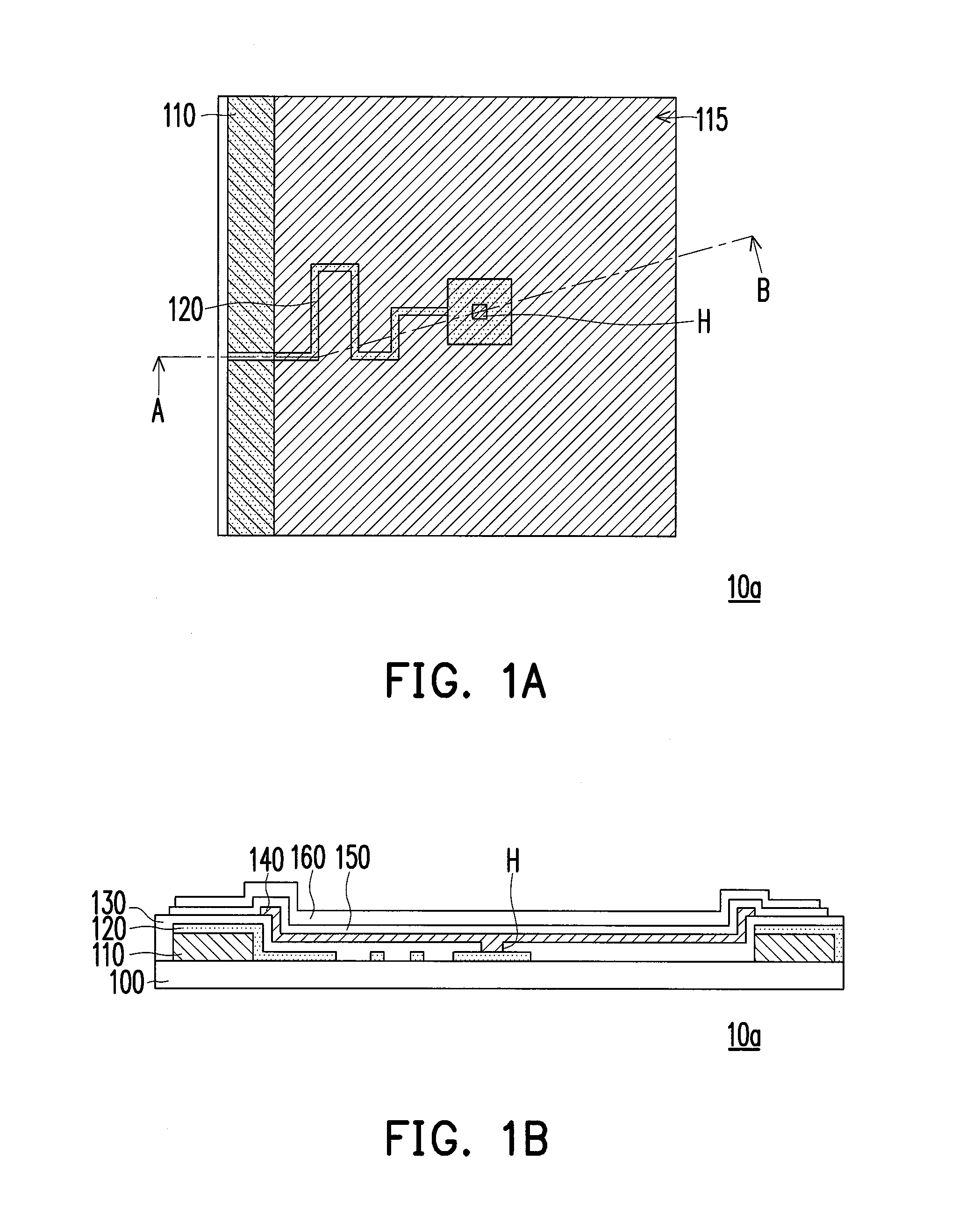
[0032]FIG. 1A is a schematic top view of an organic electroluminescent device in the first embodiment of the present invention, and FIG. 1B is a cross-sectional view of the organic electroluminescent device in FIG. 1A along a cross-sectional line A-B. Referring to FIG. 1A and FIG. 1B, the organic electroluminescent device 10a of this embodiment includes a substrate 100, an electrode line 110, a transparent impedance line 120, an insulating layer 130, a transparent electrode 140, an organic illumination layer 150 and an electrode 160. A structure formed by the transparent electrode 140, the organic illumination layer 150 and the electrode 160 of the organic electroluminescent device 10a is also called an organic luminescent unit. Besides, a luminescent zone 115 is formed between the two neighboring electrode lines 110. The transparent impedance line 120, the insulating layer 130 and the organic luminescent unit are disposed in the luminescent zone 115 to form an organic electrol...

second embodiment

[0037

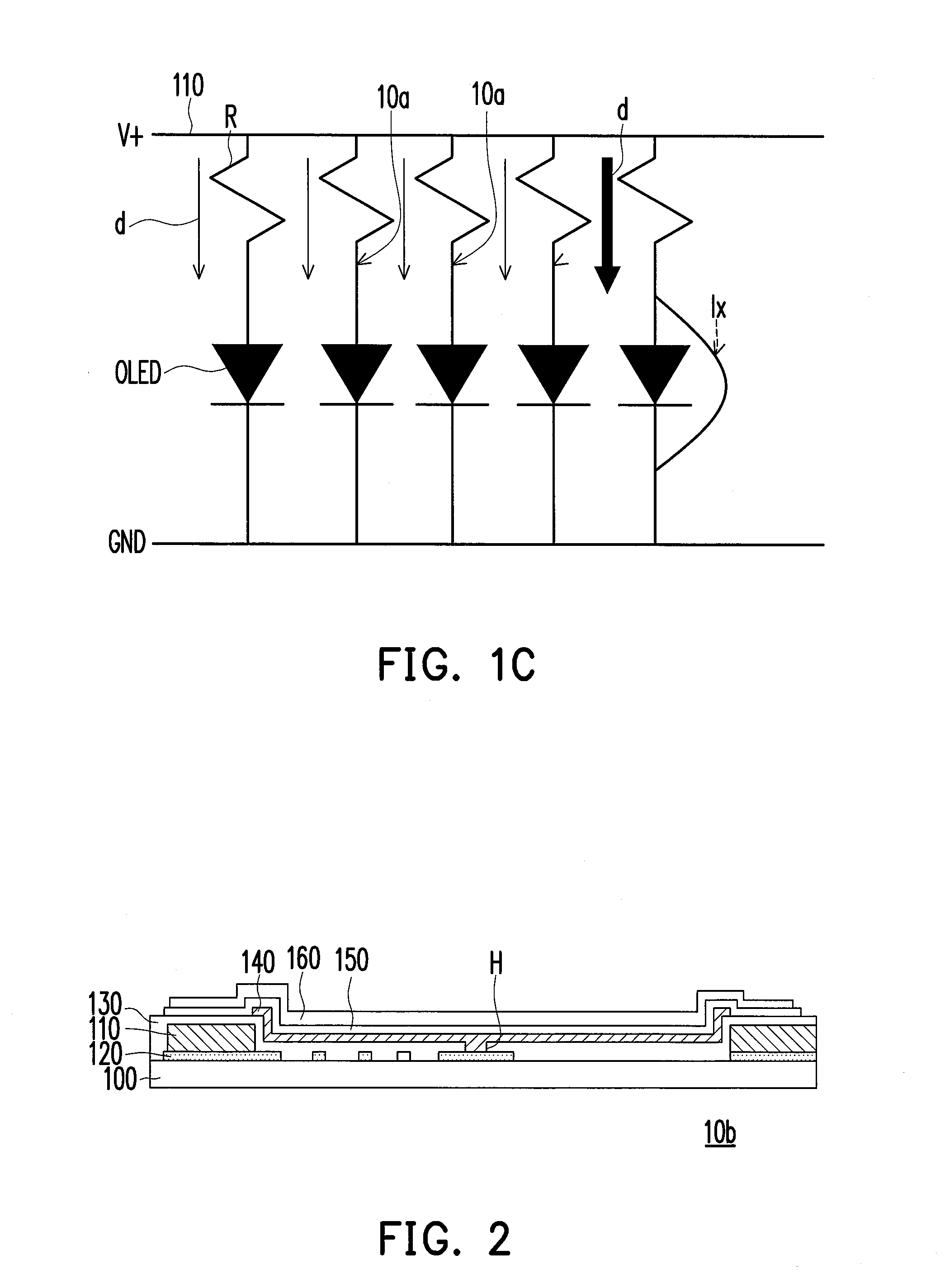
[0038]FIG. 2 is a schematic cross-sectional view of an organic electroluminescent device in the second embodiment of the present invention. Referring to FIG. 2, in the organic electroluminescent device 10b, the transparent impedance line 120 is disposed on the substrate 100 first, and the electrode line 110 is disposed on the transparent impedance line 120. In other words, in this embodiment, the transparent impedance line 120, the electrode line 110, the insulating layer 130, and the transparent electrode 140, the organic illumination layer 150 and the electrode 160 in the organic luminescent unit are disposed in sequence on the substrate 100. However, in the first embodiment, the electrode line 110 of the organic electroluminescent device 10a is formed on the substrate 100 first, and then the transparent impedance line 120 is formed, so that the transparent impedance line 120 covers the electrode line 110.

third embodiment

[0039

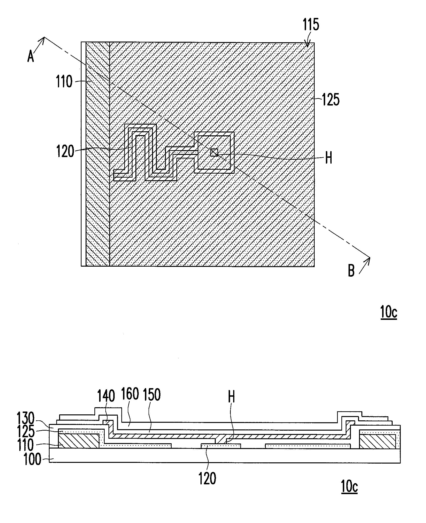
[0040]FIG. 3A is a schematic top view of an organic electroluminescent device in the third embodiment of the present invention, and FIG. 3B is a cross-sectional view of the organic electroluminescent device in FIG. 3A along a cross-sectional line A-B. Referring to FIG. 3A and FIG. 3B, the organic electroluminescent device 10c includes a patterned transparent conductive layer 125, and a part of the patterned transparent conductive layer 125 overlaps the electrode line 110. The patterned transparent conductive layer 125 and the transparent impedance line 120 are located at the same layer, but the patterned transparent conductive layer 125 is only connected to one end of the transparent impedance line 120 away from the contact hole, where the patterned transparent conductive layer 125 is disposed in an area in the luminescent zone 115 surrounding the transparent impedance line 120, and a part of the patterned transparent conductive layer 125 overlaps the electrode line 110, as sho...


PUM


Abstract

An organic electroluminescent device including an electrode line, a transparent impedance line, an insulating layer, a transparent electrode, an organic illumination layer and an electrode is provided. The electrode line is disposed on a substrate and next to a luminescent zone. The transparent impedance line is disposed in the luminescent zone on the substrate and electrically connected to the electrode line. The insulating layer completely covers the substrate and has a contact hole. The transparent electrode completely covers the luminescent zone and is disposed on the insulating layer. The transparent impedance line and the transparent electrode are electrically connected to each other through the contact hole. The organic illumination layer is disposed on the transparent electrode. The electrode is disposed on the organic illumination layer. Thus, the illumination of the organic electroluminescent device can be more uniform and the aperture ratio is increased.

Description

CROSS-REFERENCE TO RELATED APPLICATION[0001]This application claims the priority benefit of Taiwan application serial no. 100147475, filed on Dec. 20, 2011. The entirety of the above-mentioned patent application is hereby incorporated by reference herein and made a part of this specification.BACKGROUND OF THE INVENTION[0002]1. Field of the Invention[0003]The present invention generally relates to a luminescent device, in particular, to an organic electroluminescent device.[0004]2. Description of Related Art[0005]Currently, information communication industry has become the mainstream industry, particularly various portable communication display products are key points to be developed. As a communicating interface between human and information, the development of a flat panel display is particularly important. An organic electroluminescent display is an organic electroluminescent device formed by organic light emitting diodes (OLED), and with advantages of self-emission, wide viewing ...

Claims


Application Information

Patent Timeline
Patent Type & Authority Patents(United States)
IPC IPC(8): H05B33/12H01L23/64
CPCH01L23/64H05B33/12H01L2924/00H01L2924/0002G09G3/3208
Inventor LIN, CHEN-CHICHEN, CHIEH-WEICHIN, YUAN-CHENLIN, CHUN-LIANG
Owner OPTRONIC SCI LLC
Why Eureka
Try Eureka