Electronic device, and method controlling electronic power supply

a technology of electronic power supply and electronic device, which is applied in the direction of liquid/fluent solid measurement, instruments, transportation and packaging, etc., can solve the problem that the operation of charging a secondary battery cannot be controlled in an appropriate manner, the amount of electric current required is limited, and the amount of electric current required is larg

Inactive Publication Date: 2015-05-12
NIKON CORP
View PDF31 Cites 468 Cited by
  • Summary
  • Abstract
  • Description
  • Claims
  • Application Information

AI Technical Summary

Benefits of technology

[0009]In addition, another object of the present invention is to provide a technology such that, while a secondary battery is being charged with an electric current at a predetermined rating, an operation which requires a large amount of electric current exceeding this predetermined rating can be executed appropriately.
[0013]Based on the above method controlling the electronic power supply according to an aspect of the present invention, it is possible to appropriately perform an operation which requires a large amount of electric current exceeding a predetermined rating, while a secondary battery is being charged with an electric current at the predetermined rating.

Problems solved by technology

However, there is a limit on the amount of electric current provided from an external host device via a USB cable.
Therefore, depending on the operation mode of digital cameras and the like, there is a problem in that the operation of charging a secondary battery cannot be controlled in an appropriate manner.
Therefore, there is a problem in that an operation, which requires a large amount of electric power exceeding the predetermined rating, cannot be performed appropriately while the secondary battery is being charged via a USB cable.
For example, operations such as the driving of a lens barrel cannot be performed appropriately while the secondary battery is being charged via a USB cable.

Method used


Image

  • Electronic device, and method controlling electronic power supply
  • Electronic device, and method controlling electronic power supply
  • Electronic device, and method controlling electronic power supply

Examples


first embodiment

[0023]Hereunder, the present invention is described with reference to the diagrams.

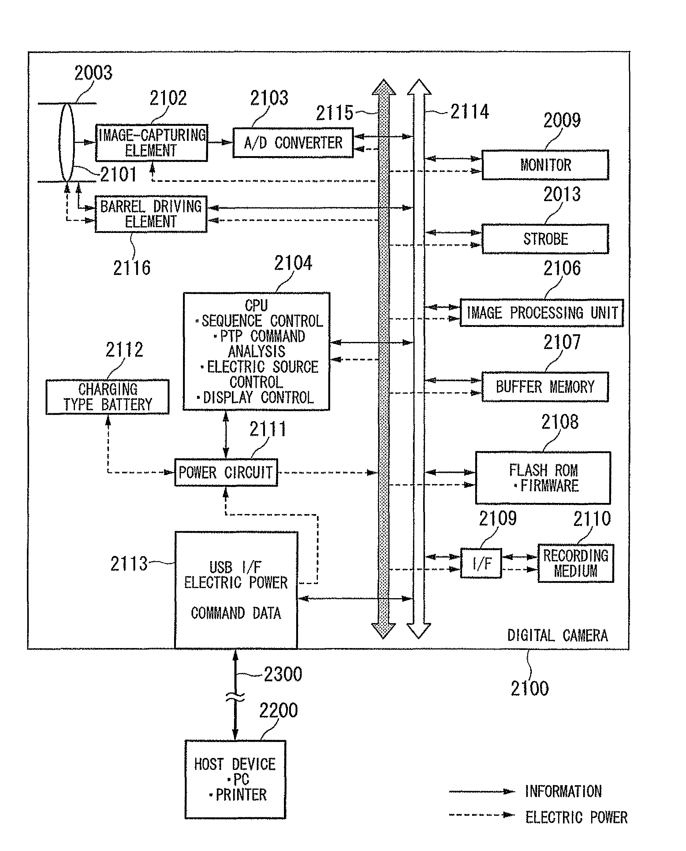
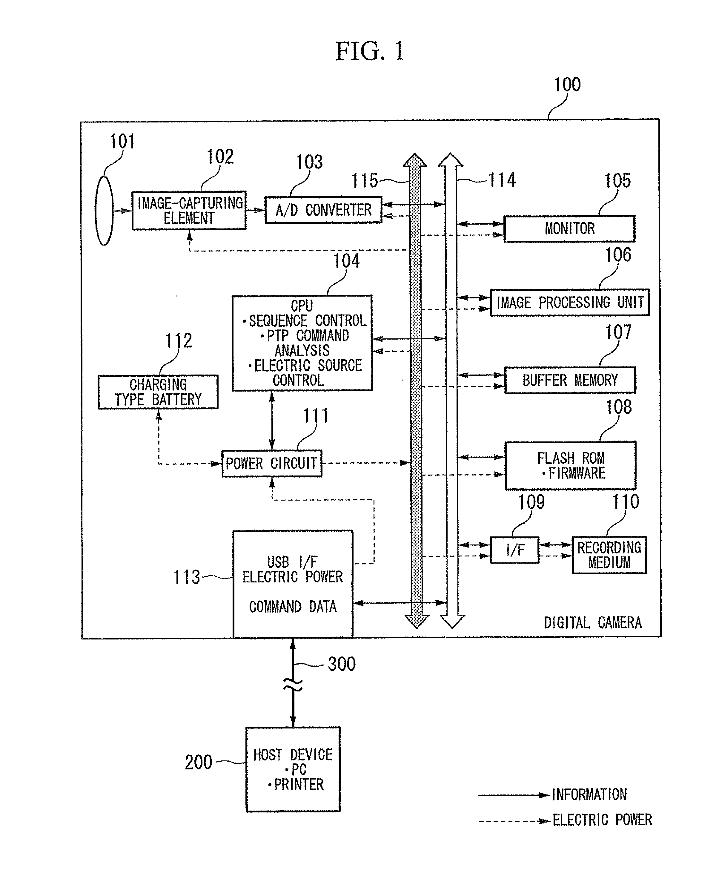
[0024]FIG. 1 is an overall structural diagram of a digital camera according to the present embodiment.

[0025]A digital camera 100 includes an imaging lens 101, an image-capturing element 102, an A / D (Analog / Digital) converter 103, a CPU (Central Processing Unit) 104, a monitor 105, an image processing unit 106, a buffer memory 107, a flash ROM (Read Only Memory) 108, a recording medium I / F (Interface) 109, a recording medium 110, a power circuit 111, a charging type battery 112, a USB I / F 113, a bus 114, and a DCC (Direct Current Cable) 115.

[0026]In addition, the digital camera 100 communicates with a host device 200 such as a PC or a printer via a USB cable 300. In addition, the digital camera 100 receives a supply of electricity from the host device 200.

[0027]The A / D converter 103 converts an image of a subject, which is formed on the image-capturing element 102 through the imaging lens 101, into a d...


PUM


Abstract

An electric device including: a connecting unit connected to a connection line supplying an electric power of a predetermined rating and transmitting and receiving an information; a charging unit conducting a charging of a charging battery connected to an own device, by the electric power supplied by the connection line; an electric supplying unit supplying an electric power to a recording medium storing an information; a reading-and-writing unit performing a reading-and-writing operation of the recording medium; and an electronic source controlling unit performing a control of the electric power supplied to the charging unit, when the reading-and-writing unit performs the reading-and-writing operation of the recording medium, according to an access request to the recording medium via the connection line.

Description

BACKGROUND OF THE INVENTION[0001]1. Field of the Invention[0002]The present application relates to an electronic device, which is driven by a secondary battery (a chargeable battery), and a method controlling an electronic power supply for this electronic device.[0003]The present application claims priority on Japanese Patent Application No. 2009-158764, filed Jul. 3, 2009; and on Japanese Patent Application No. 2009-163596, filed Jul. 10, 2009; the content of which is incorporated herein by reference.[0004]2. Description of the Related Art[0005]Conventionally, a technology is known which charges a secondary battery, which is embedded in an electronic device such as a digital camera, through a USB (Universal Serial Bus) cable. See, for example, Japanese Unexamined Patent Application, First Publication No. 2005-173822 (hereinafter referred to as Patent Document 1).[0006]However, there is a limit on the amount of electric current provided from an external host device via a USB cable. ...

Claims


Application Information

Patent Timeline
Patent Type & Authority Patents(United States)
IPC IPC(8): H02J7/00G06F13/20G06F1/26G06F1/32
CPCG06F1/266G06F1/263G06F1/3212Y02B60/1292Y02D10/00H02J7/00
Inventor KANO, GORO
Owner NIKON CORP
Why Eureka
Try Eureka