Event-based flight management system, device, and method

a flight management system and event technology, applied in the direction of process and machine control, instruments, etc., can solve the problems of flight mode change, loss of temporal awareness of upcoming events, and inability to know exactly when the aircraft will perform its next maneuver, etc., to achieve good temporal awareness and/or situational awareness

Active Publication Date: 2015-05-26
ROCKWELL COLLINS INC
View PDF9 Cites 15 Cited by
  • Summary
  • Abstract
  • Description
  • Claims
  • Application Information

AI Technical Summary

Benefits of technology

[0007]The embodiments disclosed herein present a novel and non-trivial event-based flight management system, device, and method for generating and presenting one or more flight management strips on a visual display unit. With the embodiments disclosed herein, a sequence of FMS event strips may be presented to the pilot so that he or she may be informed of the next action, allowing him or her to maintain good temporal awareness and / or situational awareness of both the current and future state of the aircraft.

Problems solved by technology

Even if the pilot is successful in scanning and integrating all of the above information presented in different locations in the cockpit, he or she may not know exactly when the aircraft will perform its next maneuver.
In addition to “getting behind the aircraft,” the inability of the pilot to maintain situational awareness of what the FMS is doing may lead to pilot to ask the classic question, “Why did the aircraft do that?”
Instead, the issue may be “why” the aircraft did something at a certain point in time, thereby indicating a possible loss of temporal awareness of upcoming route and / or flight mode changes on the part of the pilot.

Method used


Image

  • Event-based flight management system, device, and method
  • Event-based flight management system, device, and method
  • Event-based flight management system, device, and method

Examples


Embodiment Construction

[0017]In the following description, several specific details are presented to provide a thorough understanding of the embodiments of the invention. One skilled in the relevant art will recognize, however, that the invention can be practiced without one or more of the specific details, or in combination with other components, etc. In other instances, well-known implementations or operations are not shown or described in detail to avoid obscuring aspects of various embodiments of the invention.

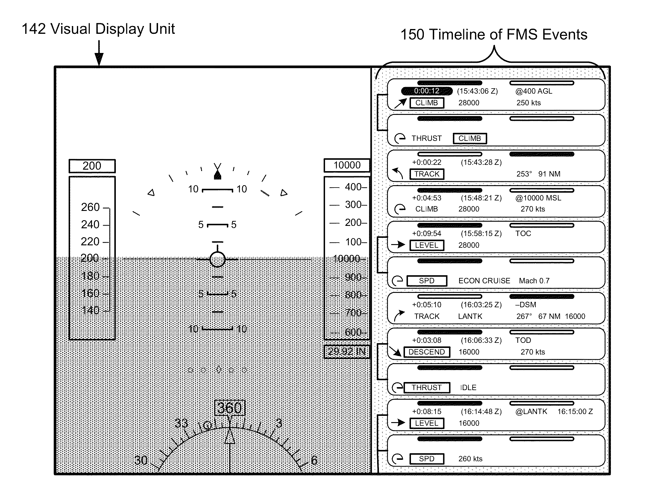
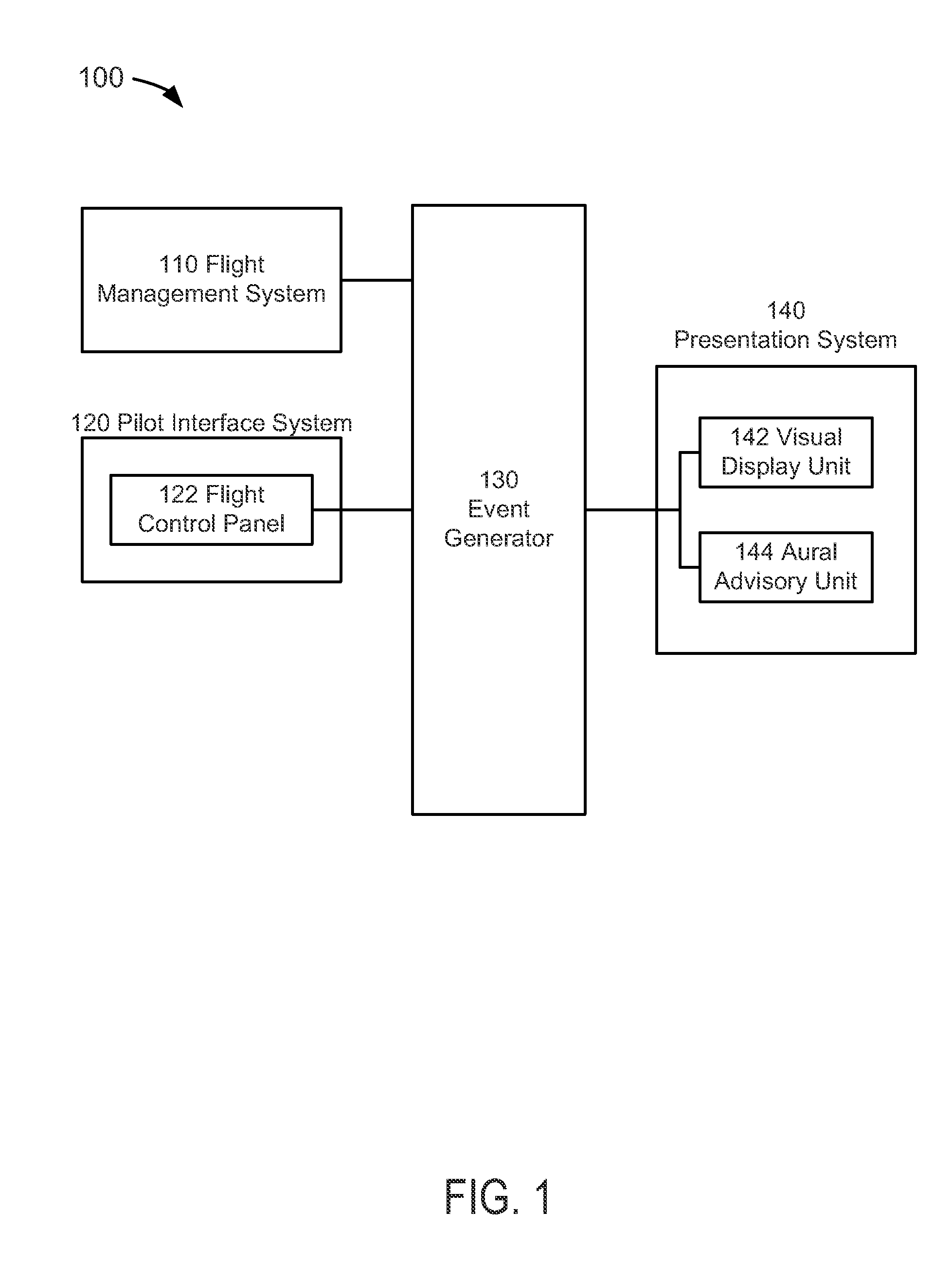
[0018]FIG. 1 depicts a block diagram of an event-based flight management system suitable for implementation of the techniques described herein. The event-based flight management system 100 of an embodiment of FIG. 1 includes flight management system (“FMS”) 110, a pilot interface system 120, an event generator (“EG”) 130, and a presentation system 140.

[0019]In an embodiment of FIG. 1, the FMS 110 may perform a variety of functions performed to help the crew in the management of the flight; these...


PUM


Abstract

Present novel and non-trivial system, device, and method for generating and presenting one or more flight management strips on a visual display unit are disclosed. An event generator (“EG”) is configured to receive flight management data representative of one or more future vertical mode actions or future lateral mode actions, generate event data representative of one or more flight management strips, and provide the event data to a presentation system for the subsequent display of flight management strip(s). Each future vertical mode action may be comprised of a vertical FMS event or a speed / thrust FMS event, and each future lateral mode action may be comprised of a lateral FMS event. Also, each flight management strip could be informative of one FMS event and comprised of at least one commencement time row and one FMS event row for displaying time and event information, respectively.

Description

BACKGROUND OF THE INVENTION[0001]1. Field of the Invention[0002]This invention pertains generally to the field of aircraft display units that present flight information to the pilot or flight crew of an aircraft.[0003]2. Description of the Related Art[0004]In present-day aircraft operations, whenever a flight management system (“FMS”) is an active source of navigation information, pilots have the ability to integrate information from several sources in order to understand how the aircraft is operating now and how it will operating next. For example, a primary flight display (“PFD”) could display current lateral, vertical, and speed / thrust flight modes, armed lateral and vertical flight modes, an FMS flight plan target altitude, and an FMS target airspeed. An FMS route window or “legs” page could display cumulative or leg distance to each waypoint, time to each waypoint, altitude and speed constraints at each waypoint (if any exists), and an FMS calculated altitude at each waypoint. ...

Claims


Application Information

Patent Timeline
Patent Type & Authority Patents(United States)
IPC IPC(8): G01C23/00B64C19/00G08G5/00
CPCB64C19/00G01C23/005G08G5/0021G01C23/00G08G5/003G08G5/0052
Inventor BARBER, SARAH
Owner ROCKWELL COLLINS INC
Why Eureka
Try Eureka