Compact multi-resolution aerial camera system

Active Publication Date: 2015-06-02
NEARMAP AUSTRALIA PTY LTD
View PDF10 Cites 22 Cited by
  • Summary
  • Abstract
  • Description
  • Claims
  • Application Information

AI Technical Summary

Benefits of technology

[0014]Each detail camera may be angled inwards towards the center of the camera hole, thereby minim

Problems solved by technology

High overlap is therefore expensive, both in terms of flying time and processing time, and practical choices of overlap represent a compromise between cost and photomosaic accuracy.
An external pod has two key disadvantages: the pod is highly aircraft-specific, and space within the pod is constrained.
An aircraft-specific pod limits the choice of aircraft and the

Method used


Image

  • Compact multi-resolution aerial camera system
  • Compact multi-resolution aerial camera system
  • Compact multi-resolution aerial camera system

Examples


Embodiment Construction

[0099]The HyperCamera™ is a compact multi-resolution aerial camera system suitable for easy deployment in a wide range of aircraft, large and small. It is designed to be installed above a standard 20-inch camera hole, as is often provided through the floor of a survey aircraft or airborne pod.

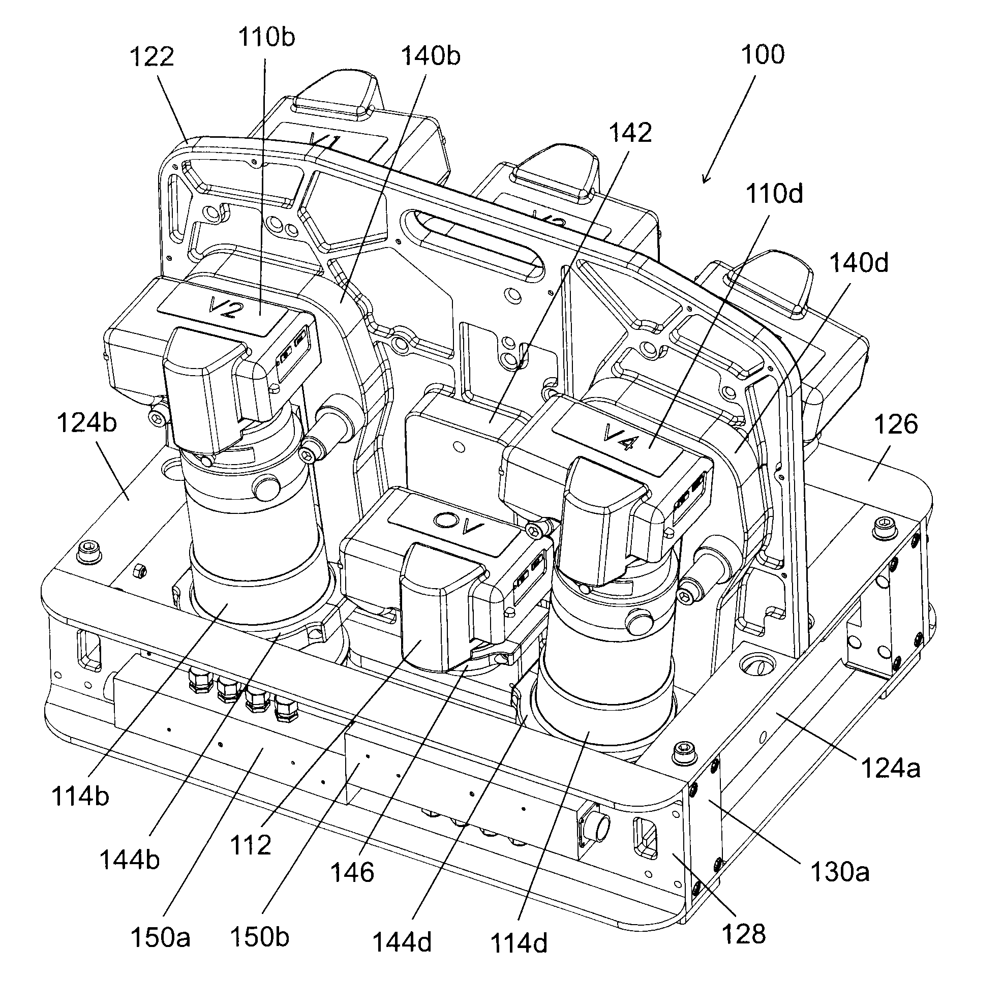
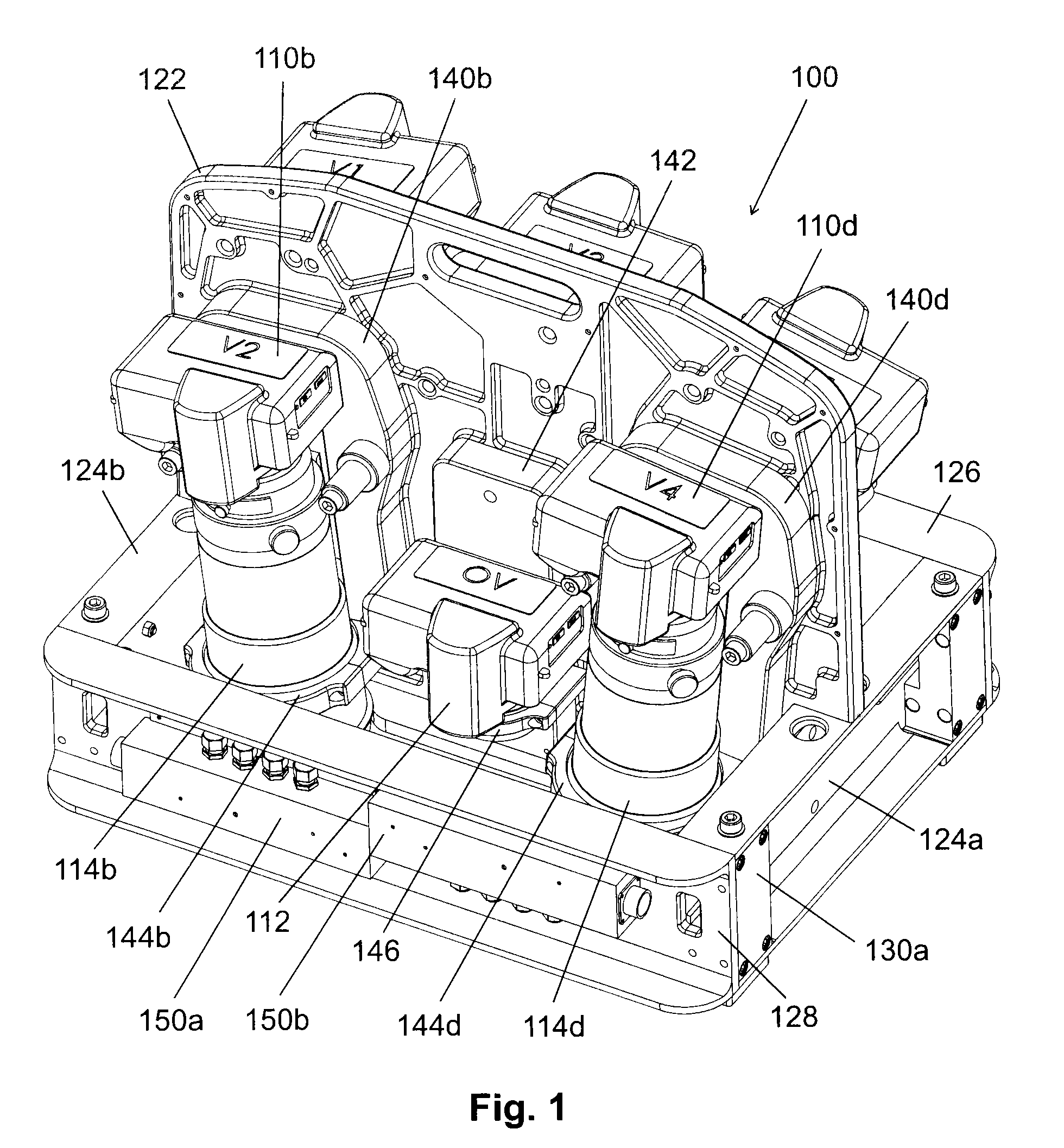
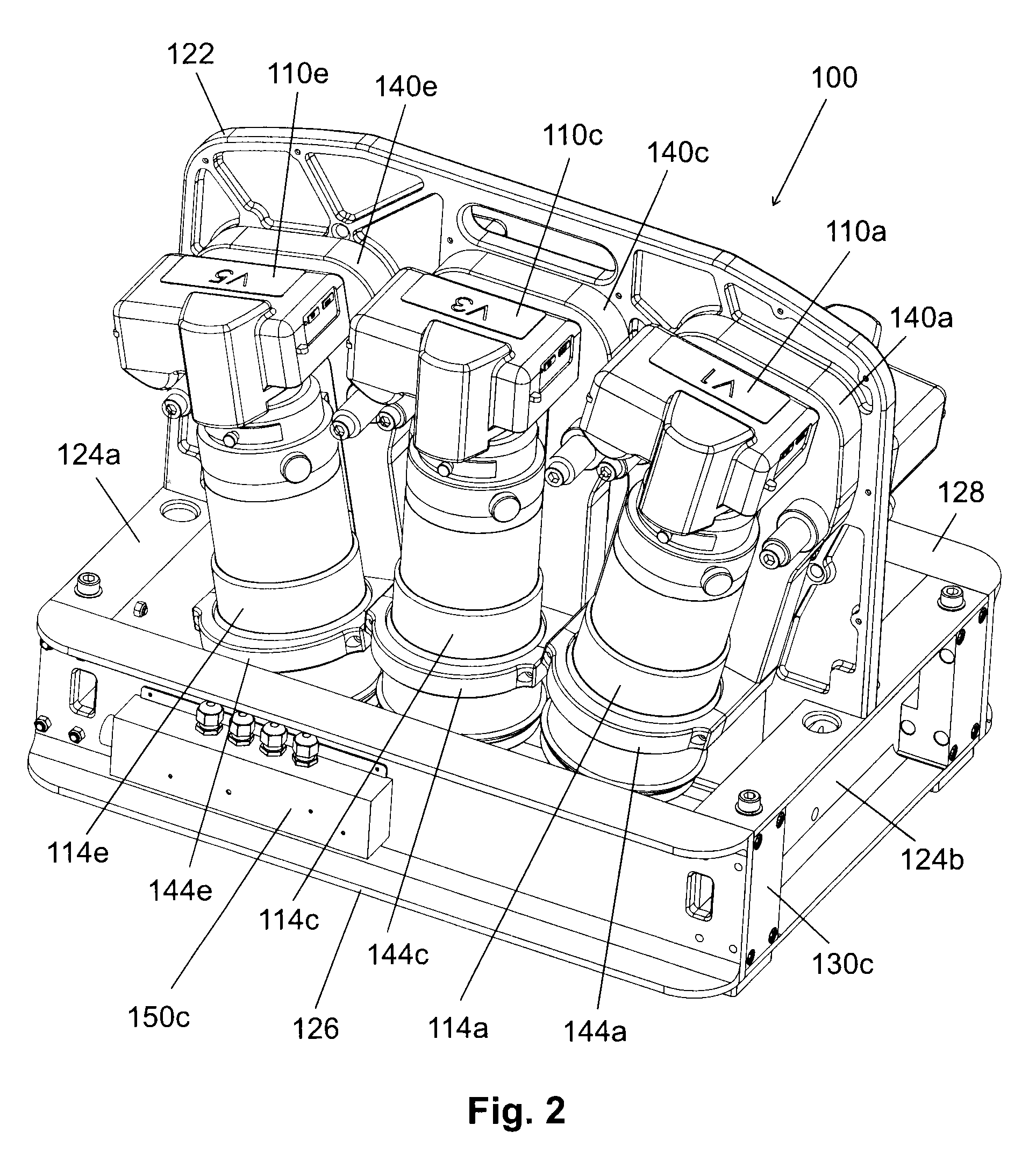
[0100]In a preferred embodiment, as illustrated in FIGS. 1 through 5, the HyperCamera comprises a camera unit 100 incorporating five detail cameras 110 and a relatively wider-angle overview camera 112. Each detail camera 110 has a detail lens 114, and the overview camera 112 has a overview lens 116.

[0101]The overview lens 116 is characterised by having a significantly wider angle than the detail lens 114. While it may be a true wide-angle lens, it may also be a normal lens or even a telephoto lens so long as it is significantly wider than the detail lens 114. Likewise, while the detail lens 114 may be a true telephoto lens, it may also be a normal lens or even a wide-angle lens so long as it is...


PUM


Abstract

A system for capturing aerial images, the system comprising at least one overview camera, a plurality of detail cameras, and a frame for holding the cameras, each detail camera having a longer focal length than the at least one overview camera, each detail camera mounted at a different angle laterally so that the fields of view of the detail cameras overlap to form an extended lateral field of view, the frame attachable to the floor of an aircraft above a camera hole, thereby providing the cameras with a view of the ground below the aircraft through the camera hole.

Description

FIELD OF THE INVENTION[0001]The present invention relates to aerial camera systems and efficient methods for creating photomosaics from aerial photos.BACKGROUND OF THE INVENTION[0002]Accurately georeferenced photomosaics of orthophotos are becoming popular alternatives to traditional pictorial maps because they can be created automatically from aerial photos, and because they show actual useful detail on the ground.[0003]The creation of accurate photomosaics from aerial photos is well described in the literature. See, for example, Elements of Photogrammetry with Application in GIS, Fourth Edition (Wolf et al.), and the Manual of Photogrammetry, Sixth Edition (American Society for Photogrammetry and Remote Sensing (ASPRS)).[0004]The creation of a photomosaic requires the systematic capture of overlapping aerial photos of the area of interest, both to ensure complete coverage of the area of interest, and to ensure that there is sufficient redundancy in the imagery to allow accurate bu...

Claims


Application Information

Patent Timeline
IPC IPC(8): G03B37/00
CPCG03B37/00G03B15/006G03B37/04
Inventor TARLINTON, MARK HAROLDBLEADS, DAVID ARNOLDLAPSTUN, PAUL
Owner NEARMAP AUSTRALIA PTY LTD
Why Eureka
Try Eureka