Pressure sensible textile and pressure sensible device thereof

a technology of sensing textiles and sensing devices, applied in the direction of positive temperature coefficient thermistors, instruments, weaving, etc., can solve the problems of limited application of relative products and circuit design limitations, and achieve the effect of increasing the sensitivity of detecting the location and magnitud

Active Publication Date: 2015-06-02
TAIWAN TEXTILE RESEARCH INSTITUTE
View PDF4 Cites 5 Cited by
  • Summary
  • Abstract
  • Description
  • Claims
  • Application Information

AI Technical Summary

Benefits of technology

[0008]According to an embodiment of the present invention, one of the two groups of low-resistance conducting wefts and warps is distributed over a side of the high-resistance conducting area, and another group of low-resistance conducting wefts and warps interweaves above and below the high-resistance conducting area alternately. Besides, a group of low-resistance conducting wefts and warps is grounded to separate the high-resistance conducting area into a coupled of pressure sensible areas to increase the sensitivity of detecting the location and magnitude of the pressure.
[0009]According to another embodiment, the pressure sensible textile can be composed of a plurality of high-resistance conducting areas. A group of low-resistance conducting wefts and warps is directly contacted with each of the plurality of high-resistance conducting areas separately, while another group of low-resistance conducting wefts and warps interweaves above and below the high-resistance conducting area. Besides, an insulating area can be utilized to totally isolate the high-resistance conducting areas in order to increase the sensitivity of detecting the location and magnitude of the pressure.
[0011]According to the embodiments above, the pressure sensible textile of the present invention can determine the location and the magnitude of the pressure source simply by laterally and longitudinally interweaving the low-resistance conducting wefts and warps over the one-layered high-resistance conducting textile, and accompanying by two scanning circuits. Therefore, the thickness and the weight of the pressure sensible textile can be substantially reduced, which improves and extends the application. Some of the examples are the pressure sensible rugs at the front door of stores, the interactive perceptive dolls, the children game carpet, the direction and speed detection carpets while people walk on them, and other various applications.

Problems solved by technology

However, limited by the circuit design, it is required a structure comprising at least two layers of the conducting wefts and warps for pressure sensing.
Therefore, the conventional conducting textile is thicker, and the application of the relative products is limited accordingly.

Method used


Image

  • Pressure sensible textile and pressure sensible device thereof
  • Pressure sensible textile and pressure sensible device thereof
  • Pressure sensible textile and pressure sensible device thereof

Examples


first embodiment

The First Embodiment

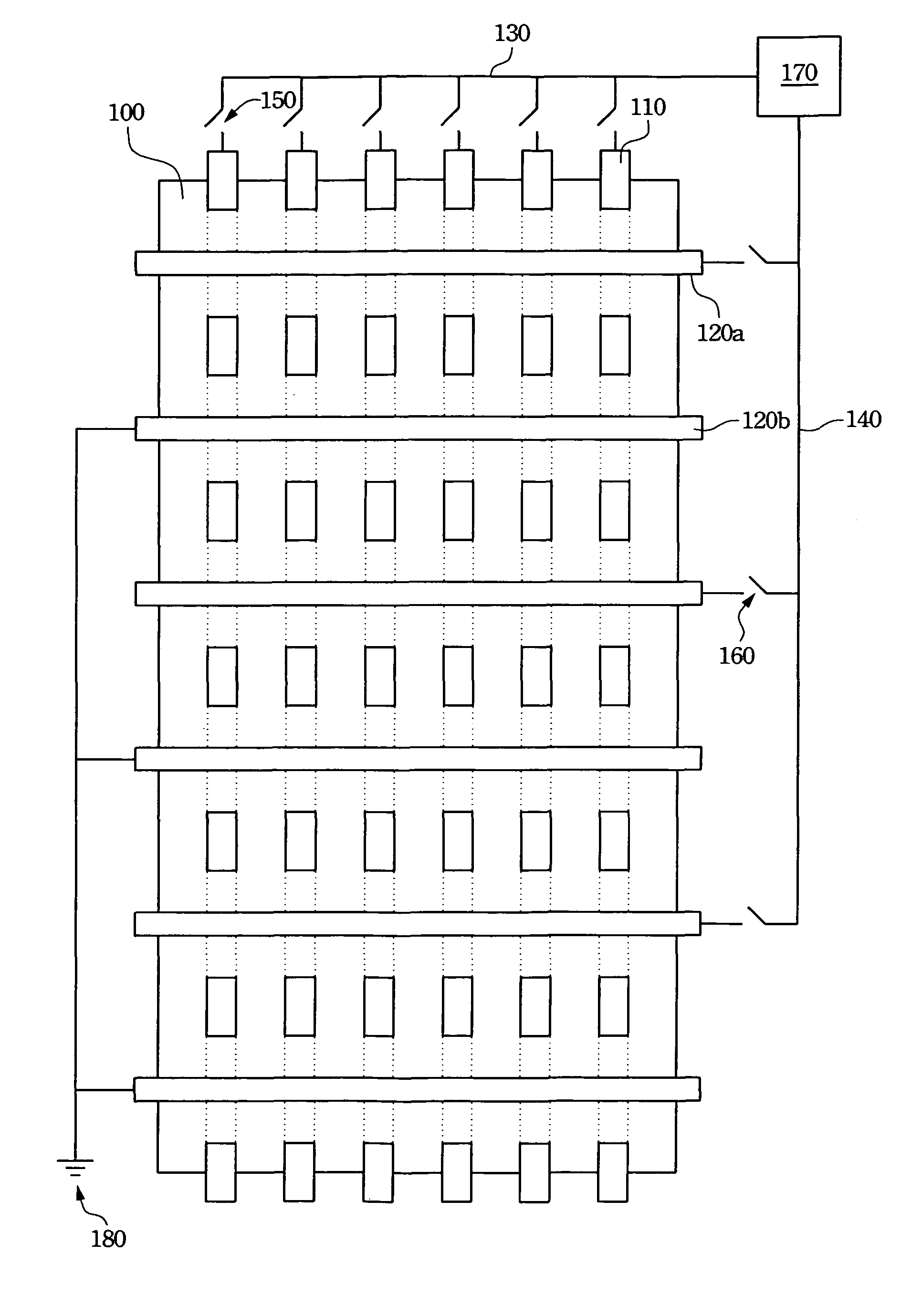
[0022]Referring to FIG. 1, a diagram of a pressure sensible textile and the corresponding pressure sensible device according to an embodiment of the present invention is illustrated.

[0023]In FIG. 1, the main textile 100 of the pressure sensible textile is composed of the high-resistance conducting wefts and warps. The low-resistance conducting warps 110 and the low-resistance conducting wefts 120a and 120b are crisscross distributed over the main textile 100. The low-resistance conducting warps 110 interweave above and below the main textile 100, and the low-resistance conducting wefts 120a and 120b are fixed only at one side of the main textile 100, for example, fixed at the upper side. The low-resistance conducting warps 110 and the low-resistance conducting wefts 120a and 120b are separated by the main textile 100 so that they do not contact to each other in order to prevent short circuits. The weaving scheme of the main textile 100 may be any conventional wea...

second embodiment

The Second Embodiment

[0032]Please refer to FIG. 3. FIG. 3 illustrates a diagram of the pressure sensible textile and the corresponding pressure sensible device according to another embodiment of the present invention.

[0033]In FIG. 3, the structure of the pressure sensible textile is different from the pressure sensible textile displayed in FIG. 1. In FIG. 3, the main textile 300 of the pressure sensible textile is composed of the pressure sensible area 310 formed by the high-resistance conducting wefts and warps and the insulating area 320 formed by the common yarn. The low-resistance conducting warps 330 are mainly located below the main textile 300 with a short section located above the pressure sensible area 310 in order to directly contact to the high-resistance conducting wefts and warps of the pressure sensible area 310. The low-resistance conducting wefts 340 are mainly located above the main textile 300 and directly contact to a side of the pressure sensible area 310. The ma...


PUM

PropertyMeasurementUnit
breaking elongationaaaaaaaaaa
pressureaaaaaaaaaa
resistanceaaaaaaaaaa

Abstract

A pressure sensible textile has at least a high-resistance conducting area and two groups of low-resistance conducting wefts or warps contacting the high-resistance area directly. The two groups of low-resistance conducting wefts or warps cross each other and do not contact with each other directly. Furthermore, two scanning circuits can be electrically connected to the two groups of low-resistance conducting wefts or warps. Then, a controller is added to the two scanning circuits to obtain a pressure sensible device.

Description

RELATED APPLICATIONS[0001]The present application is based on, and claims priority from, Taiwan Application Serial Number 94135384, filed Oct. 11, 2005, the disclosure of which is hereby incorporated by reference herein in its entirety.BACKGROUND[0002]1. Field of Invention[0003]The present invention relates to a conducting textile and related detecting device. More particularly, the present invention relates to a pressure sensible textile and related pressure sensible device.[0004]2. Description of Related Art[0005]With the prosperity of technology, the conducting textile comprising the conducting wefts and warps and the common weaving fiber has been developed. Integrated with the electronic transmission sensor and switches, the conducting textile may be utilized to construct the electronic sensing units and to apply broadly to the sensing devices, for example, the pressure sensing devices.[0006]Generally, it is usually required in the structure of the pressure sensible conducting t...

Claims


Application Information

Patent Timeline
Patent Type & Authority Patents(United States)
IPC IPC(8): D03D15/00D03D1/00D03D13/00D03D15/56G06F3/045H01C3/12
CPCH01C3/12D03D1/0088D03D13/004D03D15/08G06F3/045D03D2700/0137D03D15/56
Inventor TANG, CHIEN-FAHUANG, CHING-TANG
Owner TAIWAN TEXTILE RESEARCH INSTITUTE
Why Eureka
Try Eureka