
Mineral identification using sequential decomposition into elements from mineral definitions

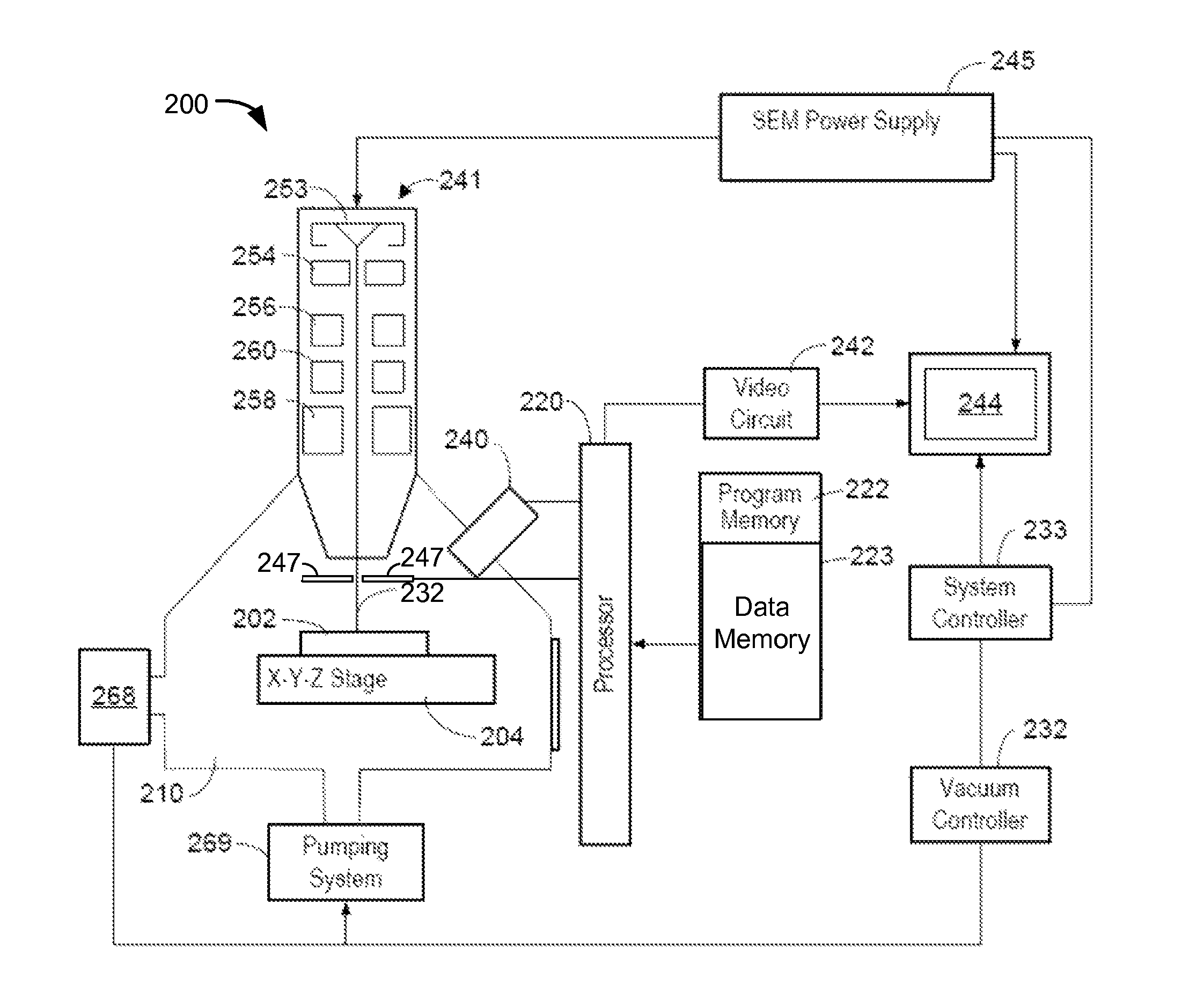
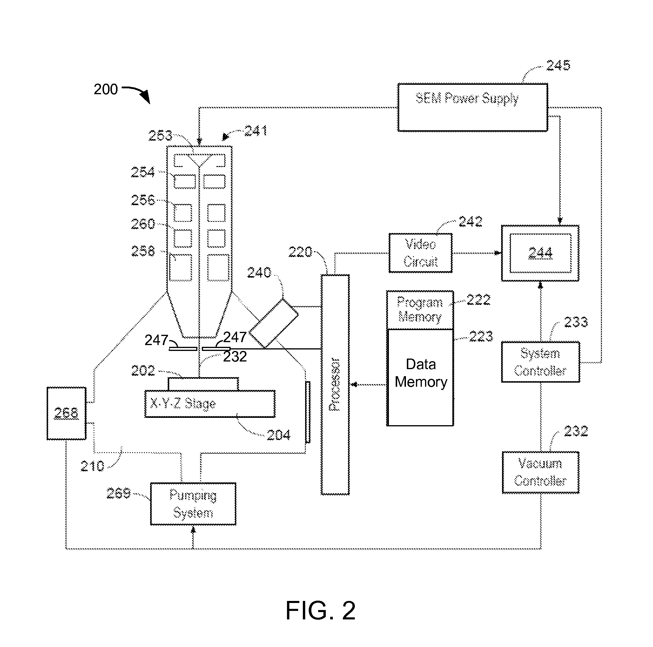
a mineral and decomposition technology, applied in the field of mineral identification using sequential decomposition into elements from mineral definitions, can solve the problems of inability to define a universal rule database, difficulty in identifying whether an x-ray spectrum contains na or zn, and difficulty in defining the approach. to achieve the effect of improving mineral identification

Active Publication Date: 2015-06-02
FEI CO
View PDF96 Cites 7 Cited by
  • Summary
  • Abstract
  • Description
  • Claims
  • Application Information

AI Technical Summary

Problems solved by technology

Thus, it is not possible to define a universal rules database for an arbitrary number of X-ray counts using the QEMSCAN.
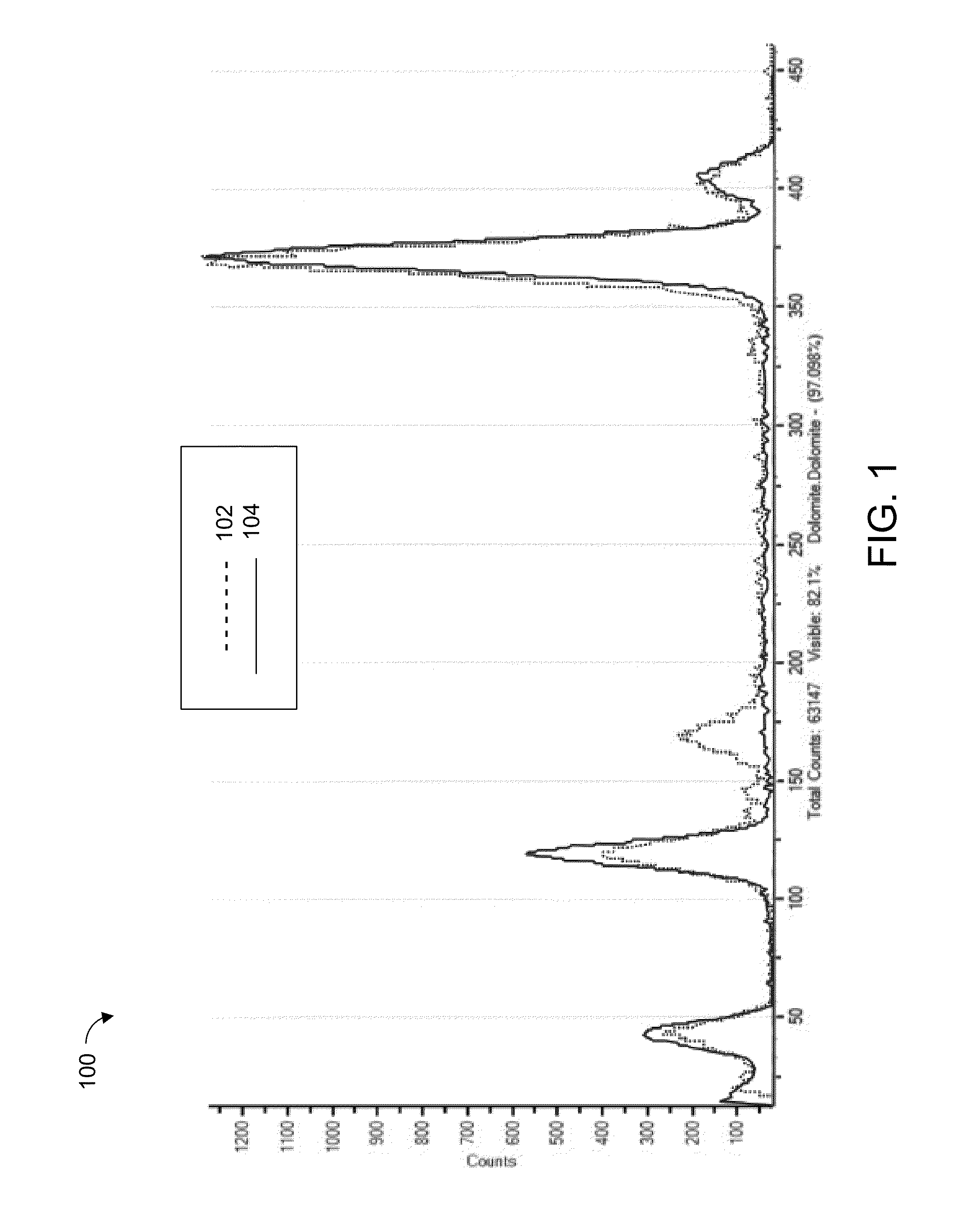
This approach becomes increasingly difficult as fewer x-ray counts are used, because the signal-to-noise ratio drops below the point where discrimination between certain elements is possible.
If the concentration of Zn is low, the second x-ray peak becomes indistinguishable from the background, and as a result, identifying whether an x-ray spectrum contains Na or Zn becomes difficult.
Because it can be difficult to identify individual elements, the mineral definitions being matched may have to be sufficiently flexible to accommodate elements that are not in the mineral, but that can be misidentified for elements in the mineral.
Because both EDS detectors and BSE detectors each have advantages, it is sometimes useful to use both BSE and x-ray spectra to accurately identify a mineral.
Using both signals, however, requires more analysis time, which may not be available in commercial applications.
A problem of using a comparison on a channel-by-channel basis is that there is no guarantee that all required peaks in the mineral spectrum are present in the measured spectrum.
This misclassification would likely go undetected without significant quality assurance performed by the operator of the software.
Another difficulty with current mineral identification systems is that, many minerals are as non-stoichiometric mixtures.
In the prior art, this was typically ignored, and each mineral defined as having a specific proportion of elements, leading to misidentification of minerals.

Method used


Image

  • Mineral identification using sequential decomposition into elements from mineral definitions
  • Mineral identification using sequential decomposition into elements from mineral definitions
  • Mineral identification using sequential decomposition into elements from mineral definitions

Examples


Embodiment Construction

[0042]Several of the techniques described herein are separately novel and may be used independently or together.

[0043]In some embodiments, mineral identification is improved by comparing the unknown spectrum to the element list in each of multiple definitions. A similarity metric is determined for each mineral definition, and the unknown mineral is identified with the mineral definition having the best similarity metric that exceeds a threshold. That is, rather than trying to match the unknown spectrum with a combination of all possible elemental spectra, the unknown spectrum is matches with only those elements in the mineral definition, one mineral definition at a time

[0044]In some embodiments, mineral identification is improved by using mineral definitions that include a mean and a variation measure for the relative quantity of each element in the mineral, and / or for some other measured value, such as atomic weight, of the mineral. A similarity metric, such as a match probability,...


PUM

PropertyMeasurementUnit
compositionaaaaaaaaaa
spectrumaaaaaaaaaa
spectraaaaaaaaaaa

Abstract

Mineral definitions each include a list of elements, each of the elements having a corresponding standard spectrum. To determine the composition of an unknown mineral sample, the acquired spectrum of the sample is sequentially decomposed into the standard spectra of the elements from the element list of each of the mineral definitions, and a similarity metric computed for each mineral definition. The unknown mineral is identified as the mineral having the best similarity metric.

Description

TECHNICAL FIELD OF THE INVENTION[0001]The present invention relates generally to methods and structures for identifying minerals using charged particle beam systems and x-ray spectroscopy systems.BACKGROUND OF THE INVENTION[0002]Mineral analysis systems, such as the QEMSCAN® (Quantitative Evaluation of Minerals by Scanning electron microscopy) and MLA® (Mineral Liberation Analyzer) both from FEI Company, the assignee of the present invention, have been used for many years to analyze samples from mines to determine the presence of valuable minerals. Such systems direct an electron beam toward the sample and measure the energy of x-rays coming from the material in response to the electron beam for elemental analysis or chemical characterization of a sample. One such process is called “energy dispersive x-ray analysis” or “EDS.”[0003]EDS systems rely on the emission of X-rays from a sample to perform elemental analysis. Each element has a unique atomic structure, which produces x-rays ...

Claims


Application Information

Patent Timeline
Patent Type & Authority Patents(United States)
IPC IPC(8): H01J40/00G01N23/225H01J37/252
CPCH01J37/252G01N23/2252H01J2237/221H01J2237/24585H01J2237/2561
Inventor OWEN, MICHAEL JAMES
Owner FEI CO
Learn More