
Endoscopic system for accessing constrained surgical spaces

a constrained surgical space and endoscopic technology, applied in the field of medical equipment and surgical methods, can solve the problems of obstructing or occluded access to the surgical site, ineffectiveness, and limited visualization

Active Publication Date: 2015-06-09
SOCORRO MEDICAL
View PDF63 Cites 35 Cited by
  • Summary
  • Abstract
  • Description
  • Claims
  • Application Information

AI Technical Summary

Problems solved by technology

These overlying portions of the body may obstruct or occlude access to the surgical site.
Moreover, visualization may be limited due to over-crowding in certain constrained spaces or corporeal epicenters.
Various problems or disadvantages can be found with these current options.
Regarding inflatable retractors, they may not be effective in areas where the surrounding tissue is more rigid because the potential for sufficient volumetric expansion is not available.
An additional concern is that inflatable retractors may be susceptible to rupture.
A rupturing retractor can cause a sudden shift of instruments relative to anatomic structures which may damage anatomic structures such as blood vessels, nerves, other non-target structures, or even improperly damage the target structure.
Moreover, a rupturing retractor may release a gas into the surgical site causing discomfort or even dangerous absorption into a blood vessel.
The collapsing surgical site may leave the field obscured and the surgeon may not be aware of the damage caused.
Additionally, depending on the extent of the rupture, portions of the retractor may even get lodged in crevices in the body.
Regarding slidable expanding sleeves, positioning them once expanded can be difficult and may cause friction and abrasion of tissues.
Regarding dissection, this approach is often not desirable because the obstructing tissue is healthy and because bleeding and / or scarring could cause further complications.

Method used


Image

  • Endoscopic system for accessing constrained surgical spaces
  • Endoscopic system for accessing constrained surgical spaces
  • Endoscopic system for accessing constrained surgical spaces

Examples


first embodiment

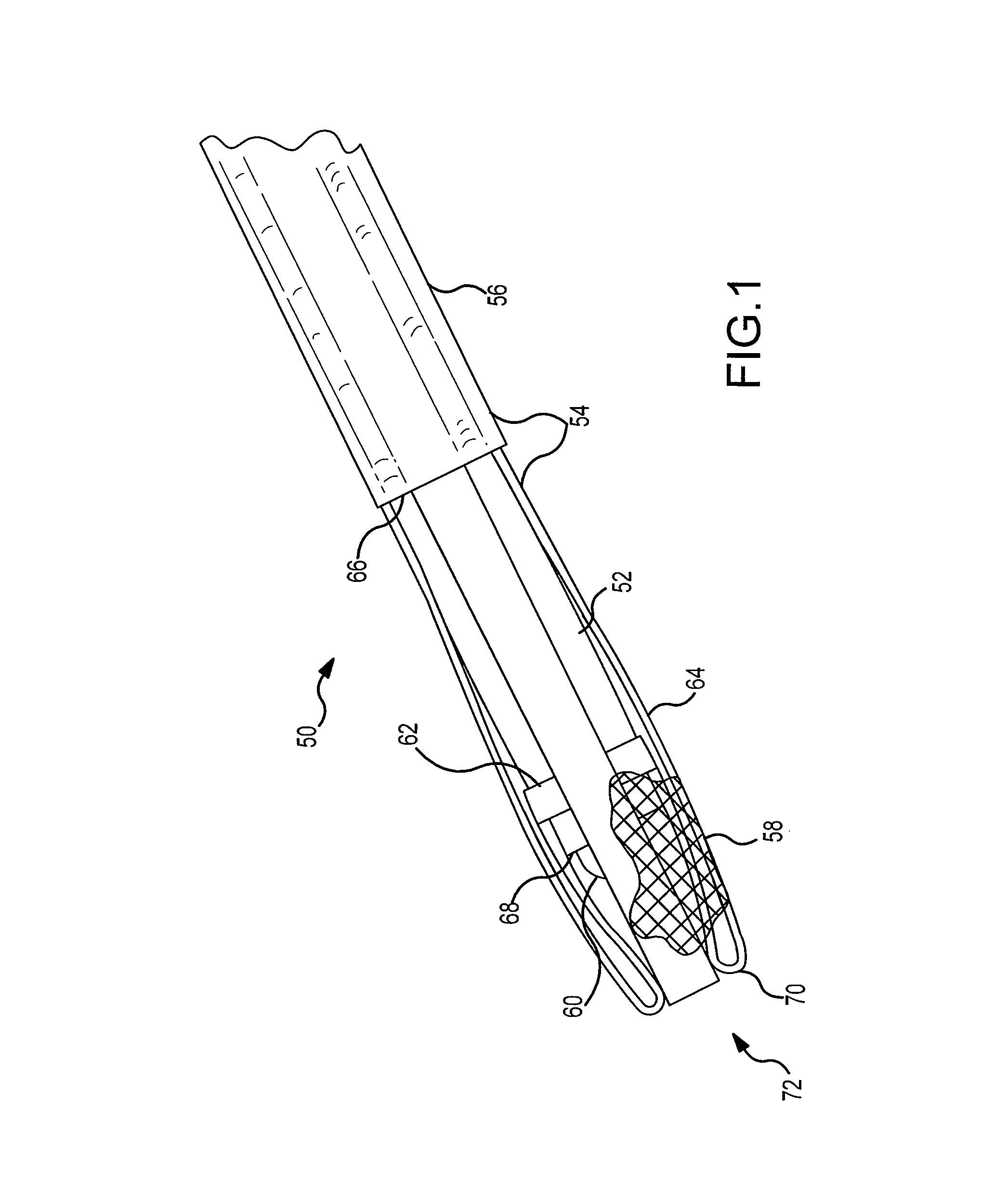
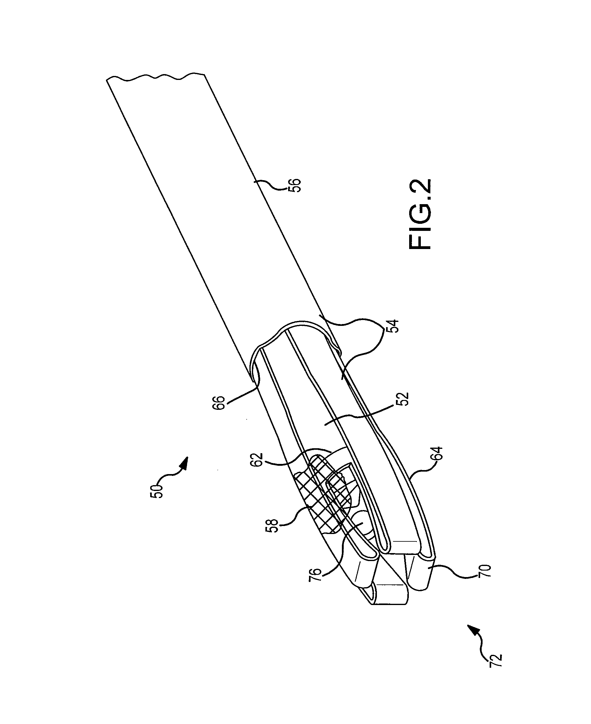
[0047]Referring now to FIGS. 1-7, an instrument 50 is shown. FIG. 1 shows a tubular body 52, a skeletal sleeve 54, an outer housing 56, a protective sheath 58, a blade 60, and a ring-like support structure 62.

[0048]The skeletal sleeve 54 includes four expandable arms 64 that extend along the longitudinal length of the tubular body 52 and are surrounded in one portion by the outer housing 56 and in another portion by a protective sheath 58. As shown, the tubular body 52 extends beyond the distal end 66 of the outer housing 56. The arms 64 extend along the tubular body 52 in a distal direction, beyond the distal end 66 of the housing 56, and beyond the distal end 68 of the tubular body 52. The arms 64 then form an integral hinge 70 by turning radially inward and returning to the ring-like support structure 62 surrounding the tubular body 52. The arms 64 are slidable between the outer housing 56 and the tubular body 52 and are connected to the ring-like support structure 62. The ring-l...

second embodiment

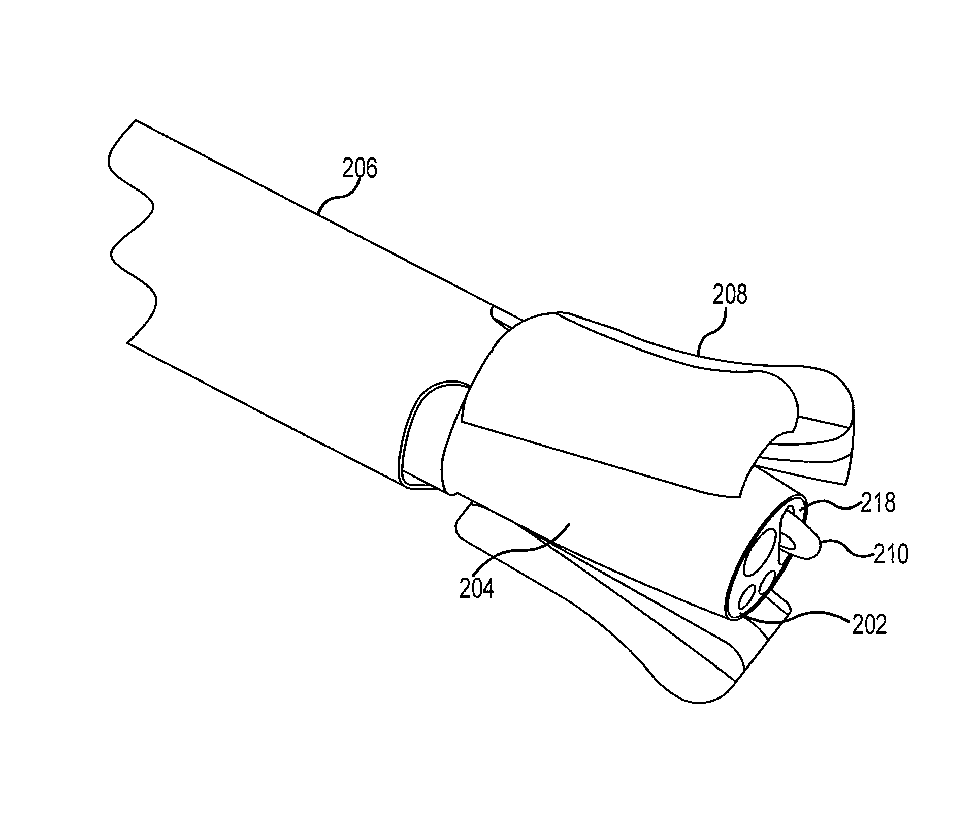
[0069]Referring now to FIGS. 8-19, an instrument 100 is shown. FIG. 8 shows a tubular body 102, a tapered sleeve 104, an outer housing 106, four ribbed retractor arms 108, and a blade 110 protruding from the tubular body 102.

[0070]The tubular body 102 is similar to that of the first embodiment. As shown, a blade 110 is protruding out of a port 118 of the tubular body 102. In this embodiment, a tapered sleeve 104 surrounds the tubular body 102 and extends over the longitudinal length of the tubular body 102. The tapered sleeve 104 slidably engages the tubular body 102 allowing for relative longitudinal telescoping movement between these two elements. As shown, the distal end 114 of the tapered sleeve 104 is positioned generally flush with the distal end 112 of the tubular body 102. The tapered sleeve 104 is surrounded by a housing 106. The housing 106 is positioned on the tapered sleeve 104 and allows for both sliding motion and rotational motion between these two elements. As shown,...


PUM


Abstract

A retractor instrument for minimally invasive surgery may include a housing with a longitudinal axis, an arm extending from a distal end of the housing, and an actuation mechanism, wherein actuation of the actuation mechanism causes radial expansion of the arm relative to the longitudinal axis. The device may be adapted for use with an endoscope or arthroscope or may be an integral part of one such scope. A method of performing surgery in constrained areas within the body is also included and may be applicable to the carpal tunnel of a wrist and palm or the cubital tunnel of an elbow.

Description

CROSS-REFERENCE TO RELATED APPLICATIONS[0001]The present application claims priority to U.S. Provisional Patent Application No. 61 / 005,837, filed on Dec. 7, 2007, entitled “Mechanically Actuated Rotational Retractor having a Protective Sheath and Method of Displacing Tissue to Access Constrained Surgical Spaces”, U.S. Provisional Patent Application No. 61 / 066,675, filed on Feb. 22, 2008, entitled “Endoscopic System and Method for Ulnar Nerve Decompression in the Cubital Tunnel”, and U.S. Provisional Application No. 61 / 050,253, filed on May 5, 2008, entitled “Surgical Methods for Decompressing Nerves in the Upper Extremities”, the contents of which are all hereby incorporated by reference herein in their entireties.FIELD OF THE INVENTION[0002]The following description relates to a medical apparatus and surgical methods. More specifically, the description relates to an instrument and to methods for minimally invasive surgical procedures in constrained spaces of the body. Even more par...

Claims


Application Information

Patent Timeline
Patent Type & Authority Patents(United States)
IPC IPC(8): A61B1/04A61B1/00A61B1/32A61B5/00A61B17/02
CPCA61B1/04A61B1/00085A61B1/32A61B5/4893A61B5/6858A61B17/0218A61B1/00087A61B1/018A61B1/317A61B17/0206A61B2017/00296A61B2017/00323A61B2017/00367A61B2017/00991A61B2017/0225A61M25/09
Inventor DIAO, EDWARDPATEL, RAJAN KASHIBHAI
Owner SOCORRO MEDICAL
Learn More