
Power base attachment

Active Publication Date: 2015-06-09
STEALTH PROD LLC
View PDF10 Cites 10 Cited by
  • Summary
  • Abstract
  • Description
  • Claims
  • Application Information

AI Technical Summary

Benefits of technology

The invention is a powered wheelchair that can be easily attached to a manual wheelchair by replacing the rear wheels with a power base attachment. The power base attachment is adjustable to fit different wheelchairs and includes an anti-tip mechanism to ensure safety and stability. This invention allows people with disabilities to easily and safely transition to a powered wheelchair without losing the ability to use their hands and feet.

Problems solved by technology

However, there are some times when manual wheelchairs are not beneficial, such as propelling long distances, managing uneven terrain, or when the user's deficits are of such degree that manual propulsion becomes painful, exhaustive, or relatively impossible given time or circumstances.
Electrically powered wheelchairs have several drawbacks including the expense, size and weight.
Financial, storage, and transportation concerns often make it not practical, or possible, for a user to have both an electric powered and manually powered wheelchair.
It is especially inconvenient when traveling to take both types of wheel chairs.
Additionally, insurance carriers generally will not pay for a user to have both types of chairs.
While power attachments for manual wheelchairs exist, those in the prior art do not replace the large rear push wheels, are not controlled by a joystick, do not keep the same height as the manual wheelchair, do not support the necessary posture and positioning of the user, and / or do not have an anti-tip / counterbalance mechanism.
None of the prior art power attachments provide for connection through the axle receivers of the standard wheelchair.
The failure to attach at the axle receiver makes the prior art attachments more difficult to attach to all types of manual wheelchairs as it generally results in a changed center of gravity for the user.
Additionally, the failure of the prior art to allow for removal of the rear wheels complicates operation of the electric powered wheelchair by making maneuverability difficult by retaining the cumbersome large rear wheels despite no longer serving a purpose.

Method used


Image

  • Power base attachment
  • Power base attachment
  • Power base attachment

Examples


Embodiment Construction

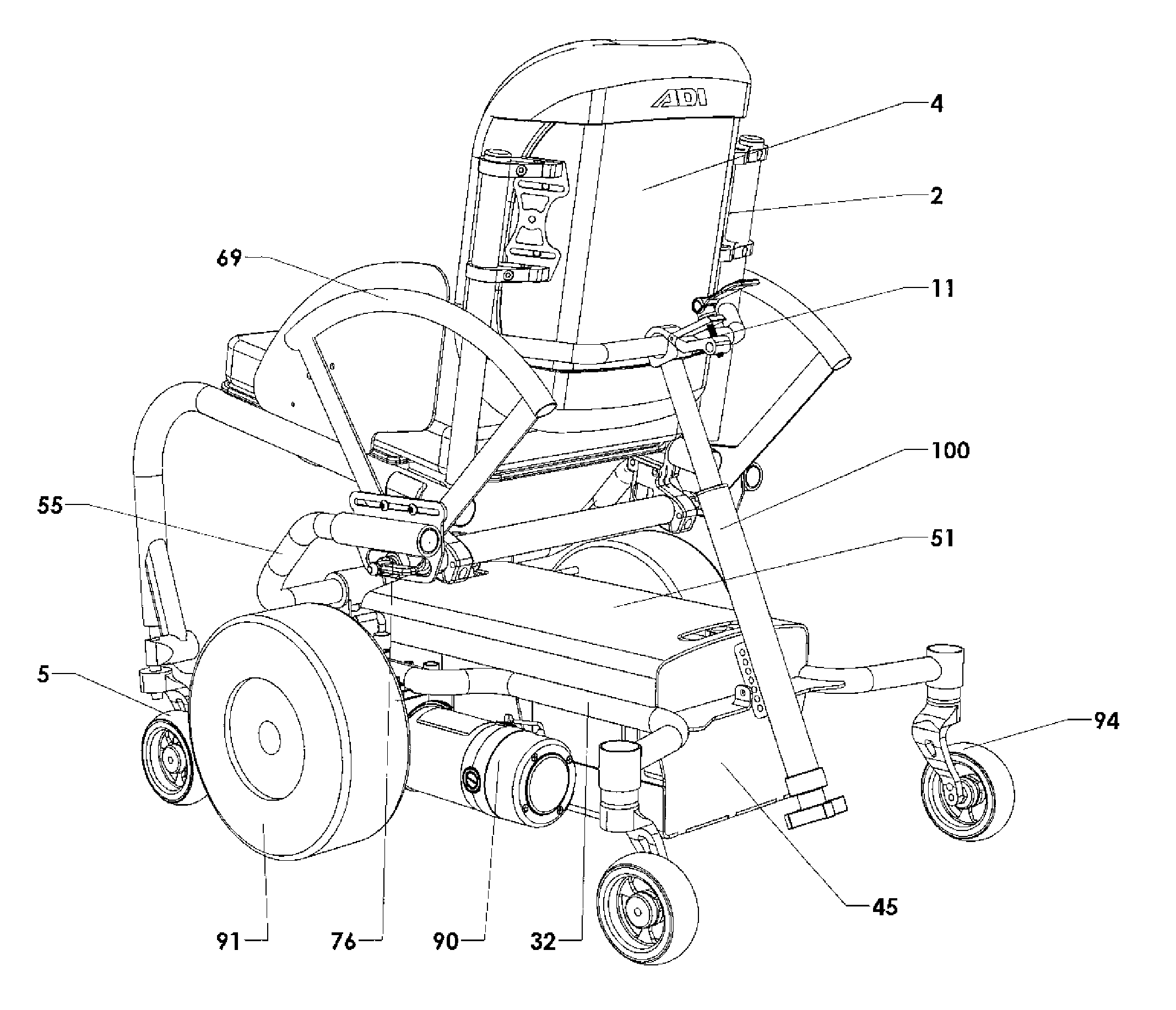
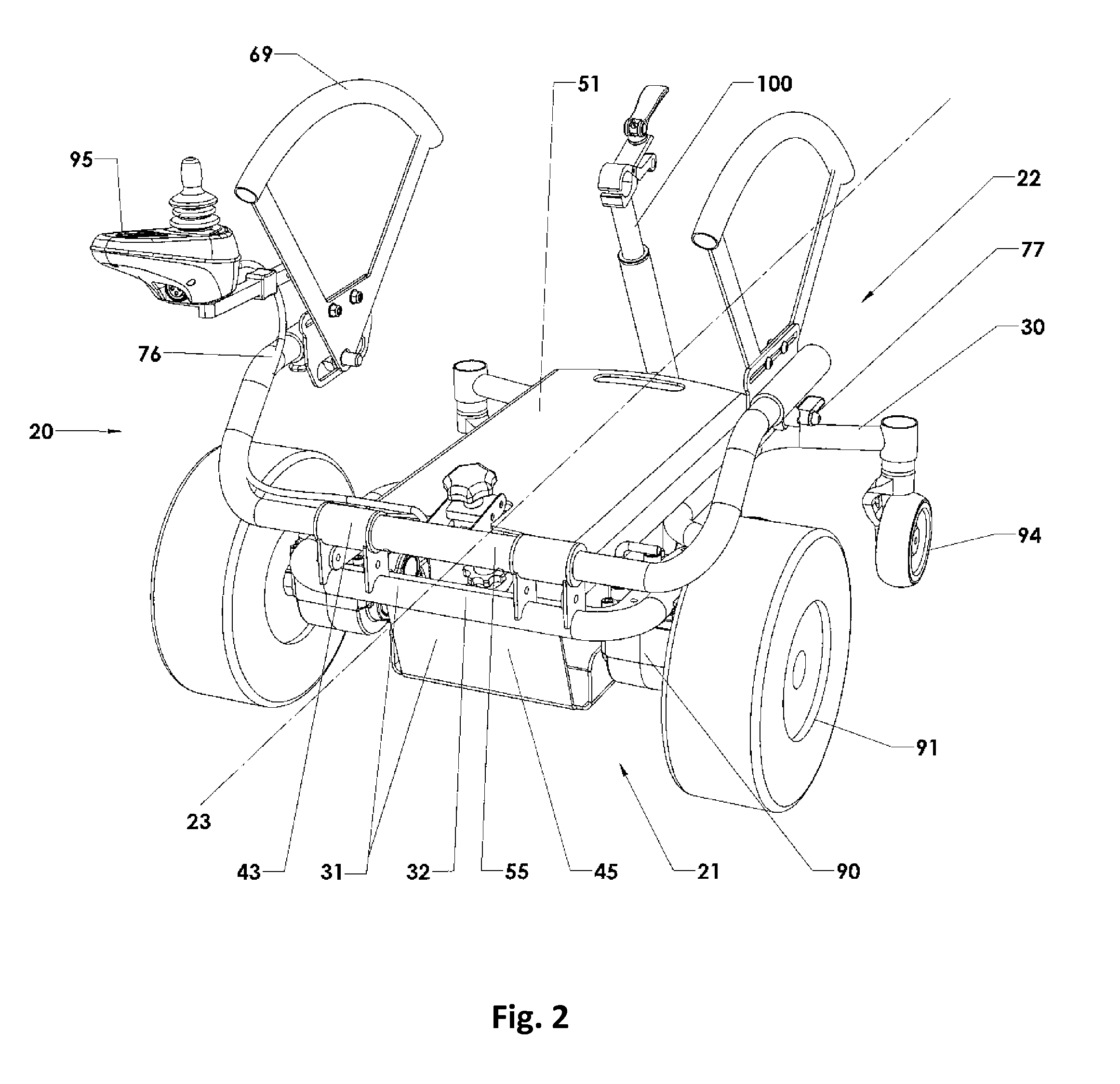
[0025]FIG. 2 discloses the power base attachment 20 which comprises a frame 30, powered drive wheels 91, rear castor wheels 94, hand rails 69, axle receiver 76, electrically powered motors 90 in electrical communication with a joystick module 95, and an anti-tip / counterbalance mechanism 100. FIGS. 3 and 4 disclose a front and rear side profile views, respectively, of the power base attachment 20 connected to the frame 2 of a manually powered wheelchair 1. The power base attachment 20 is positioned underneath the seating portion 3 of the manually powered wheelchair 1 where the front end 21 is positioned proximal to the front castor wheels 5 and the back end 22 extends beyond the backrest portion 4.

[0026]FIGS. 5 and 6 further disclose the frame 30 of power base attachment 20. The frame 30 consists of a rigid portion 31 and an adjustable portion 55. The rigid portion 31 consists of a support frame 32 and a housing 45. The support frame 32 comprises a front lateral member 33, wide longi...


PUM


Abstract

The disclosure describes an improved apparatus for converting a manually-powered wheelchair into an electrically powered wheelchair. The apparatus comprises a frame, at least one powered drive wheel, at least one motor powering said drive wheel, and at least one power base axle receiver capable of connecting with an existing axle receiver of a manually powered wheelchair. The apparatus further includes an anti-tip / counterbalance mechanism to prevent a user from losing control and falling backward when the power base attachment is connected. The apparatus uses the existing axle receiver of a manual wheelchair as a universal connection point and to maintain the center of gravity for a user.

Description

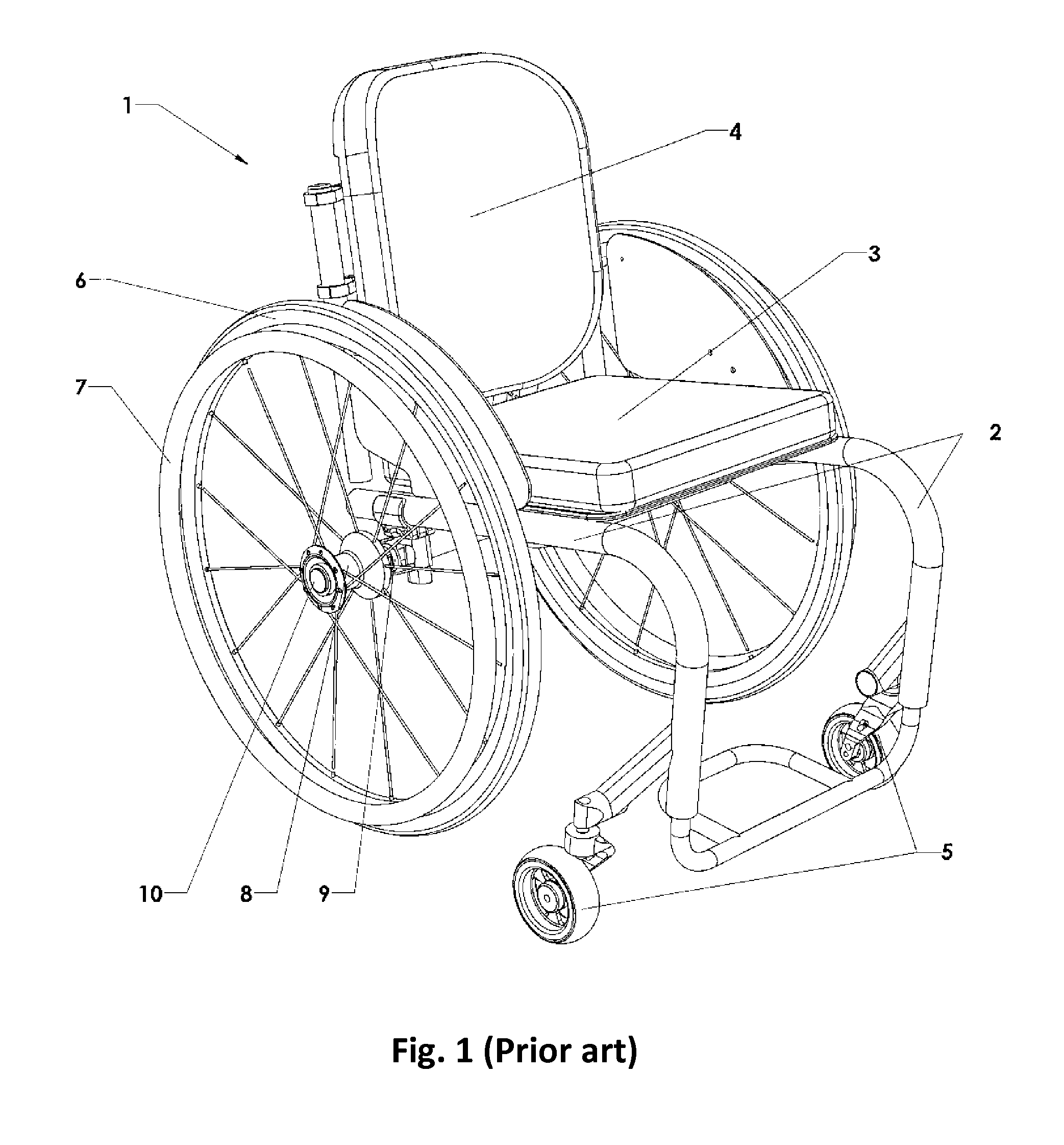
CROSS-REFERENCES TO RELATED APPLICATIONS[0001]This application is a continuation of U.S. patent application Ser. No. 14 / 121,856, filed on Mar. 17, 2014, which claims the benefit of U.S. Provisional Application Ser. No. 61 / 800,782 filed Mar. 15, 2013. The contents of these applications are incorporated by reference herein.STATEMENT REGARDING FEDERALLY SPONSORED RESEARCH OR DEVELOPMENT[0002]Not applicable.BACKGROUND OF THE INVENTION[0003]1. Field of the Invention[0004]The present invention relates to the field of wheelchairs. Specifically, this invention relates to a wheeled power attachment that converts a manually powered wheelchair into an electrically powered wheelchair.[0005]2. Description of the Related Art[0006]Manually powered wheelchairs come in a variety of sizes for a variety of purposes. Two of the most common are the standard folding wheelchair and the non-folding rigid frame wheelchair 1 (as seen in FIG. 1) designed for more active and mobile individuals. Manually powere...

Claims


Application Information

Patent Timeline
IPC IPC(8): A61G5/04A61G5/10B62B5/00F16B19/00
CPCA61G5/047A61G5/104F16B19/00A61G2005/1078A61G2005/1089A61G5/1078A61G5/1089A61G5/125
Inventor HARGRODER, TODD
Owner STEALTH PROD LLC
Learn More