Gas powered self contained portable winch

a self-contained, portable technology, applied in the field of winch, can solve the problems of compromising and dangerous positions of operators, requiring a significant amount of time to assemble the lewis winch onto the chainsaw, and limiting well-known designs, so as to achieve a higher rate of rotation, lower torque, and the effect of reducing the risk of operator injury

Inactive Publication Date: 2018-03-06
WIZARD PROD
View PDF104 Cites 2 Cited by
  • Summary
  • Abstract
  • Description
  • Claims
  • Application Information

AI Technical Summary

Benefits of technology

[0013]The transmission assembly is protected by a rigid transmission casing. Located on top of the transmission casing is a transmission knob connected to a cantilever via a shaft. By twisting the transmission knob, the cantilever rotates the shaft and toggles the transmission drive (moving it towards or away from the combustion engine). In one setting, the transmission drive engages the first transmission gear to rotate the transmission drive—providing a lower torque but a higher rate of rotation. In another setting, the transmission drive engages the second transmission gear—leading to a higher torque but slower rate of rotation for the transmission drive.
[0014]A gear assembly connects to the transmission drive regardless of the toggle setting caused by turning the transmission knob. The gear assembly includes at least one planetary gear and at least one threaded ring. Each planetary gear has a plurality of sub-gears (located between a first plate and a second plate) capable of fitting into a recess within each respective threaded ring and capable of receiving the second end of the transmission drive. By rotating the transmission drive, each sub-gear engages threads within the threaded ring providing stability and efficient rotation—which in turn provides rotational power to the clutch assembly. These components are maintained and protected through a first mounting plate and a corresponding second mounting plate.
[0015]A centrifugal clutch / brake assembly is connected to the transmission drive of the gear assembly. This assembly includes a first connecting gear which fits within a threaded clutch ring, which in turn can be engaged by a pivoting threaded arm member. A clutch cable connects with this threaded arm member, which is operated through a hand controller. By operating the hand controller, a user can apply pressure to the threaded arm member to pivot it onto the threaded clutch ring to control the rate of controlled release of the cable when under load. A clutch enclosure protects the various components of the clutch assembly and includes a rigid outer casing and a corresponding flat plate.
[0016]Moreover, the assembly serves as both a centrifugal clutch and a resistive break. The clutch includes shoes which engage a drum once the two-stroke engine reaches a predetermined speed. A drum housing coupled to the drum output plate contains a brake tab coupled to the input shaft of the transmission assembly. Each of these brake tables on the output plate ensures that the transmission input shaft will not rotate backwards. This in essence provides braking power necessary to hold tension on the cable when not retrieving line.

Problems solved by technology

While various winches have been developed for purposes of emergency rescue, there exist numerous disadvantages and limitations in well known designs.
Most notably is the fact it requires a significant amount of time to assemble the Lewis Winch onto a chainsaw.
In addition to assembly time, the operator must stand and hold the chainsaw throttle to operate the device, which can place the operator in a compromised and dangerous position.
While some all-in-one gas powered winches have been developed, these current systems also have multiple drawbacks—most notably their limited capacity due to design configuration.
Despite their larger engines both of the aforementioned examples suffer from relatively low load capacities and the fact that four-stroke engines must be kept upright to operate, which is often impossible in a rescue or off road situation.
One of the key issues in rescue and recovery after an emergency is not only the ability to move large objects to search for and recover survivors—but also how to return these bulky objects to a resting place without risking the lives of still trapped or isolated survivors.
Current winch designs, including the three currently offered gas-powered winches discussed above, fail to allow for the controlled release of the cable tension and to allow a user to have sufficient control during release of the load.
In addition, current winch designs fail to allow for a compact design which affords a durable transmission system that includes a clutch assembly capable of allowing controlled release of loads.

Method used


Image

  • Gas powered self contained portable winch
  • Gas powered self contained portable winch
  • Gas powered self contained portable winch

Examples


Embodiment Construction

[0042]The present invention will now be described more fully hereinafter with reference to the accompanying drawings, in which preferred embodiments of the invention are shown. This invention may, however, be embodied in many different forms and should not be construed as limited to the embodiments set forth herein. Rather, these embodiments are provided so that this disclosure will be thorough and complete, and will fully convey the scope of the invention to those skilled in the art. Like numbers refer to like elements throughout.

Exterior Components of the Winch

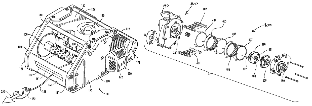
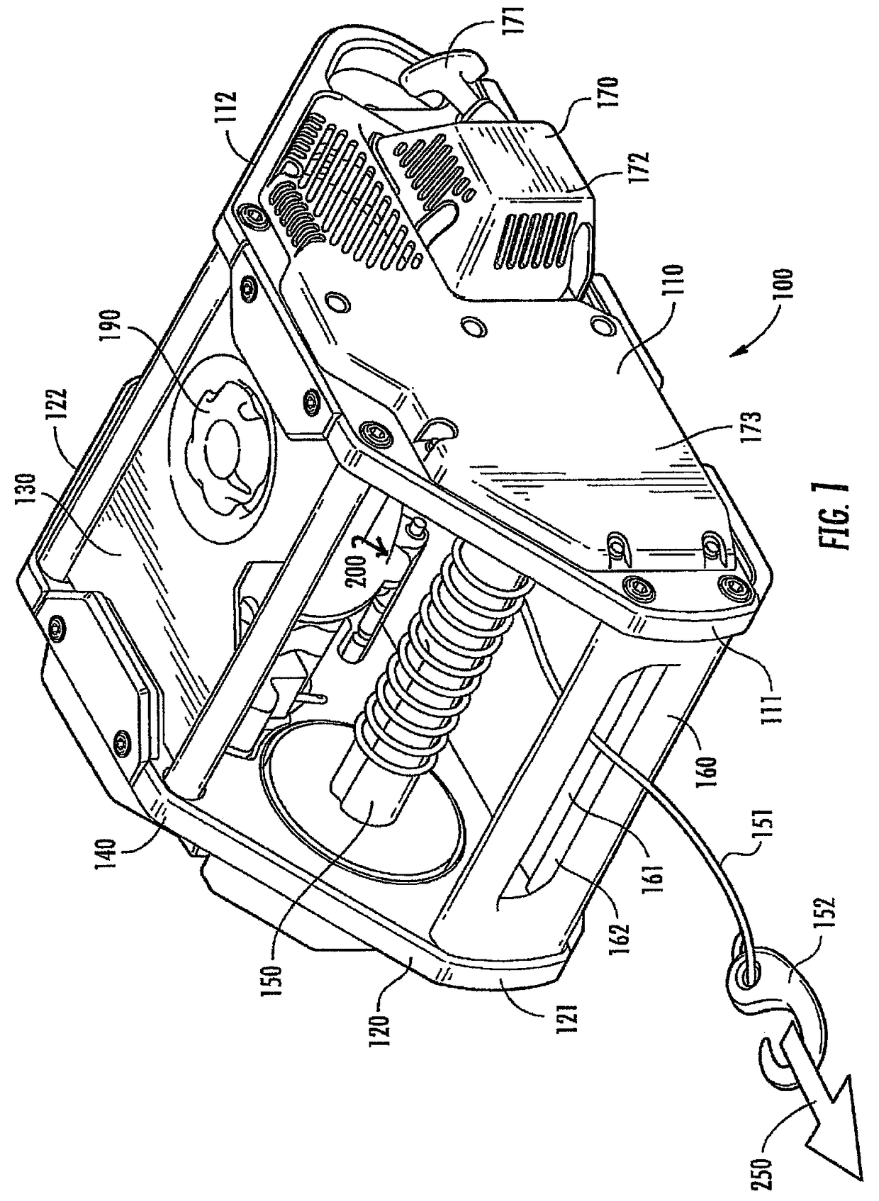
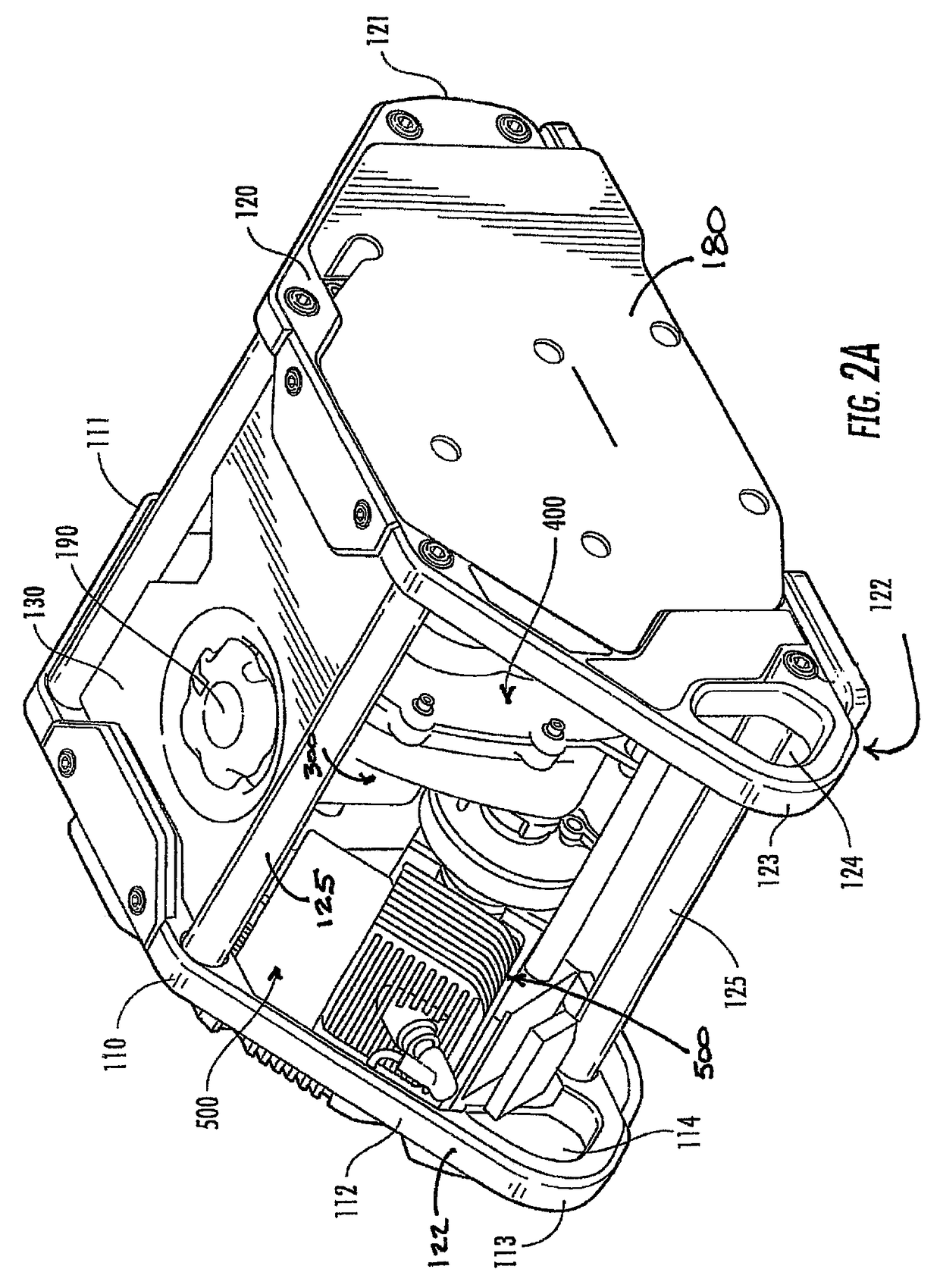
[0043]FIGS. 1, 2A and 2B offer various perspective views of an exterior casing of one embodiment of a winch 100. FIG. 1 provides a perspective front view of the winch 100. As shown, the winch 100 includes a first side wall 110 and a corresponding second side wall 120, generally parallel to the first side wall 110. The first side wall 110 is essentially flat and includes a front side 111 and a corresponding back side 112. Lik...


PUM


Abstract

A gas powered self-contained winch includes a combustion engine, a transmission assembly, a gear assembly and a clutch assembly connect to a spool capable of winding and unwinding a cable wire using forward and reverse drives. A hand controller communicates with the clutch assembly through a cable wire sufficient to control the winding and unwinding of the cable. Securing the winch for operation includes placing its center of gravity below the force line. A field changeable capstan option and remote control handle with throttle, power out lever, and kill switch are built in. A field installable hook float is provided for water rescue operations.

Description

CROSS-REFERENCE TO RELATED APPLICATIONS[0001]This application is a continuation-in-part of application Ser. No. 12 / 719,579, filed on Mar. 8, 2010, which is currently pending. The patent application identified above is incorporated herein by reference in its entirety to provide continuity of disclosure.FIELD OF INVENTION[0002]The invention is generally directed to a winch, and in particular to a self-contained and portable adjustable torque winch.BACKGROUND OF THE INVENTION[0003]A winch is typically a mechanical device used to pull in (or alternatively let out) a tensioned cable, wire, or cable. In its simplest form, a winch consists of a spool (that winds and unwinds) attached to a crank—which can either be hand or machine driven. Winches are often rigidly attached to an immobile object or heavy item such as a tow truck or steam shovel.[0004]Winches have various applications, which are determined largely by their size and underlying design considerations. Many are used for recreatio...

Claims


Application Information

Patent Timeline
Patent Type & Authority Patents(United States)
IPC IPC(8): B66D3/20B66D1/00B66D3/00B66D3/26B66D1/14B66D1/22
CPCB66D3/20B66D1/00B66D3/26B66D1/22B66D3/006B66D1/14
Inventor MORRISON, MARC ANDREW
Owner WIZARD PROD
Why Eureka
Try Eureka