Method of manufacturing an electrode for a gas discharge lamp

a gas discharge lamp and manufacturing method technology, applied in the manufacture of electrode systems, cold cathode manufacturing, electric discharge tube/lamps, etc., can solve the problems of extreme thermal load on the electrode, significant alteration of the electrode shape, and the tip of the electrode can melt back, so as to achieve the effect of increasing the ratio of luminous flux collected through an aperture to the total luminous flux of the lamp

Inactive Publication Date: 2015-06-09
KONINK PHILIPS ELECTRONICS NV +1
View PDF21 Cites 1 Cited by
  • Summary
  • Abstract
  • Description
  • Claims
  • Application Information

AI Technical Summary

Benefits of technology

[0010]An advantage of the method according to the invention is that the mass and thermal behaviour of the electrode thus manufactured are somewhere between the mass and thermal behaviour of a solid electrode design and a prior art coil-and-rod electrode design, so that the inventive electrode combines the advantages of these designs. The electrode thus manufactured is mechanically stronger than a prior art coil-and-rod electrode, and its coil can still behave as an efficient thermal radiator while the likelihood of coil breakage or opening is drastically reduced. Furthermore, the improved behaviour under high thermal load offered by the additional solid mass of the one-piece shell means that the electrode manufactured using the method according to the invention does not suffer from pronounced geometrical changes due to thermal load to the same extent as an electrode manufactured using a prior art technique. Therefore, using the method according to the invention, a favourably stable electrode with a prolonged lifetime can be manufactured in a particularly straightforward manner. The ‘one-piece shell’ is to be understood to comprise a fused portion with an uninterrupted transition to the mantle portion, even if the fused portion and mantle portion are created in separate process steps, as will be explained below. To all intents and purposes, the one-piece shell is to be regarded as a single entity. The term ‘fused portion’ is to be understood to mean re-solidified material of the electrode tip and the coil winding which has coalesced or combined during melting. The term ‘mantle portion over a remainder of the winding length’ is to be interpreted to mean that the mantle portion of the one-piece shell can extend from the fused portion to the end of the coil located towards the base of the electrode, but need not extend all the way to the end of the coil. For example, the mantle portion could terminate at a slight distance inward from the end of the coil.
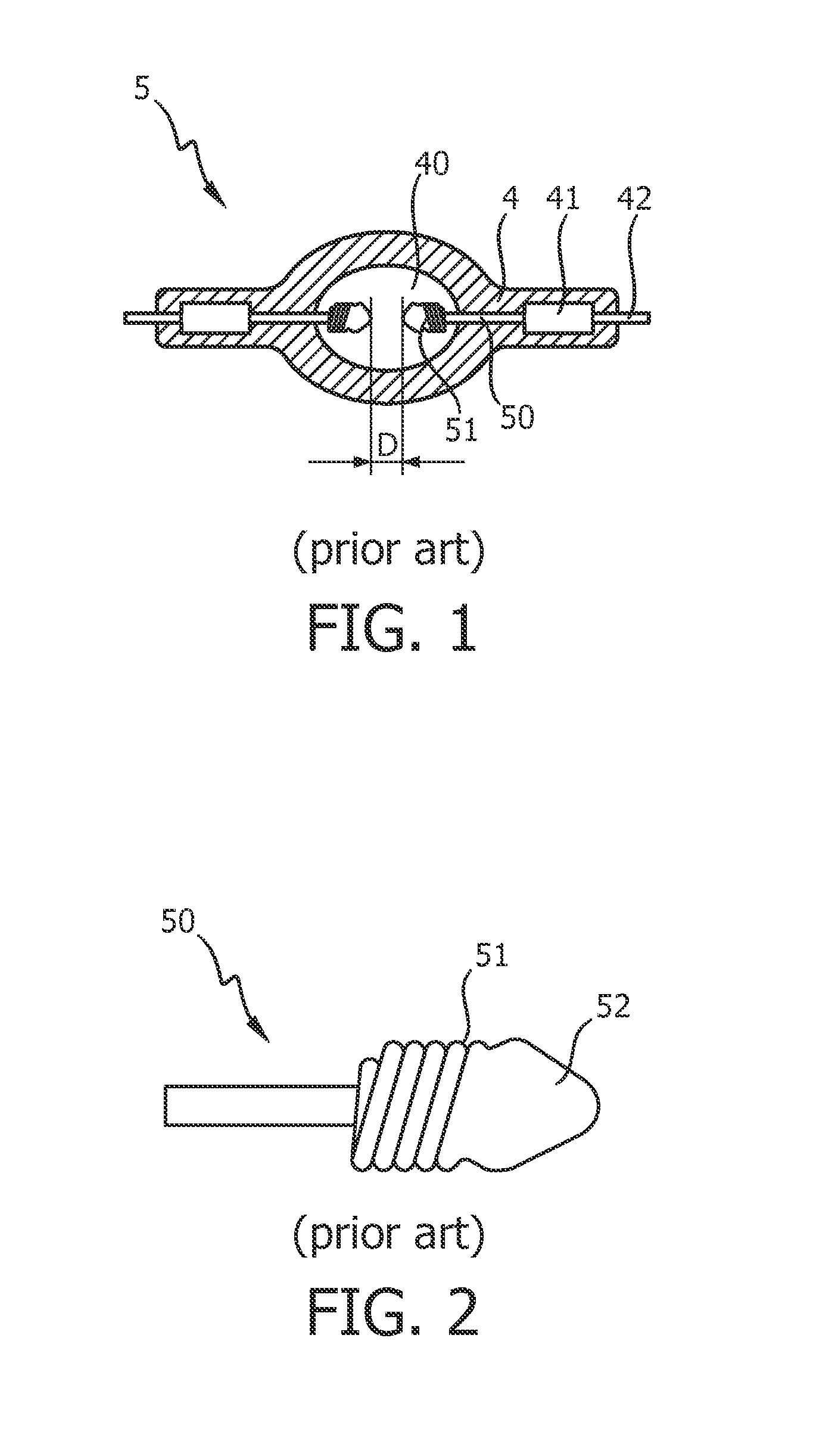
[0014]The gas-discharge lamp according to the invention exhibits an improved behaviour compared to prior art gas-discharge lamps, since the inventive electrodes are not subject to extreme deformation, i.e. the electrodes maintain their shape better. The resulting favourably short and stable arc gives an advantageously point-like source of light essentially over the lifetime of the lamp, unlike prior art lamps, in which the luminance of the arc decreases over time as the electrode separation increases as a result of the alteration in electrode shape during burn-back. The stability of the electrodes also means that the lamp according to the invention exhibits favourable lamp voltage maintenance over its lifetime.
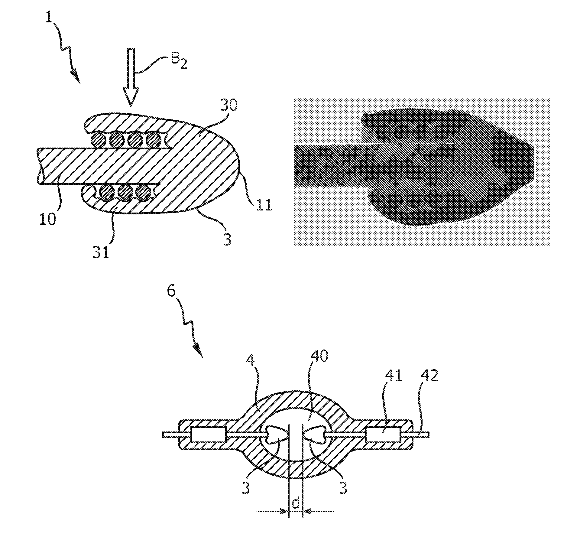
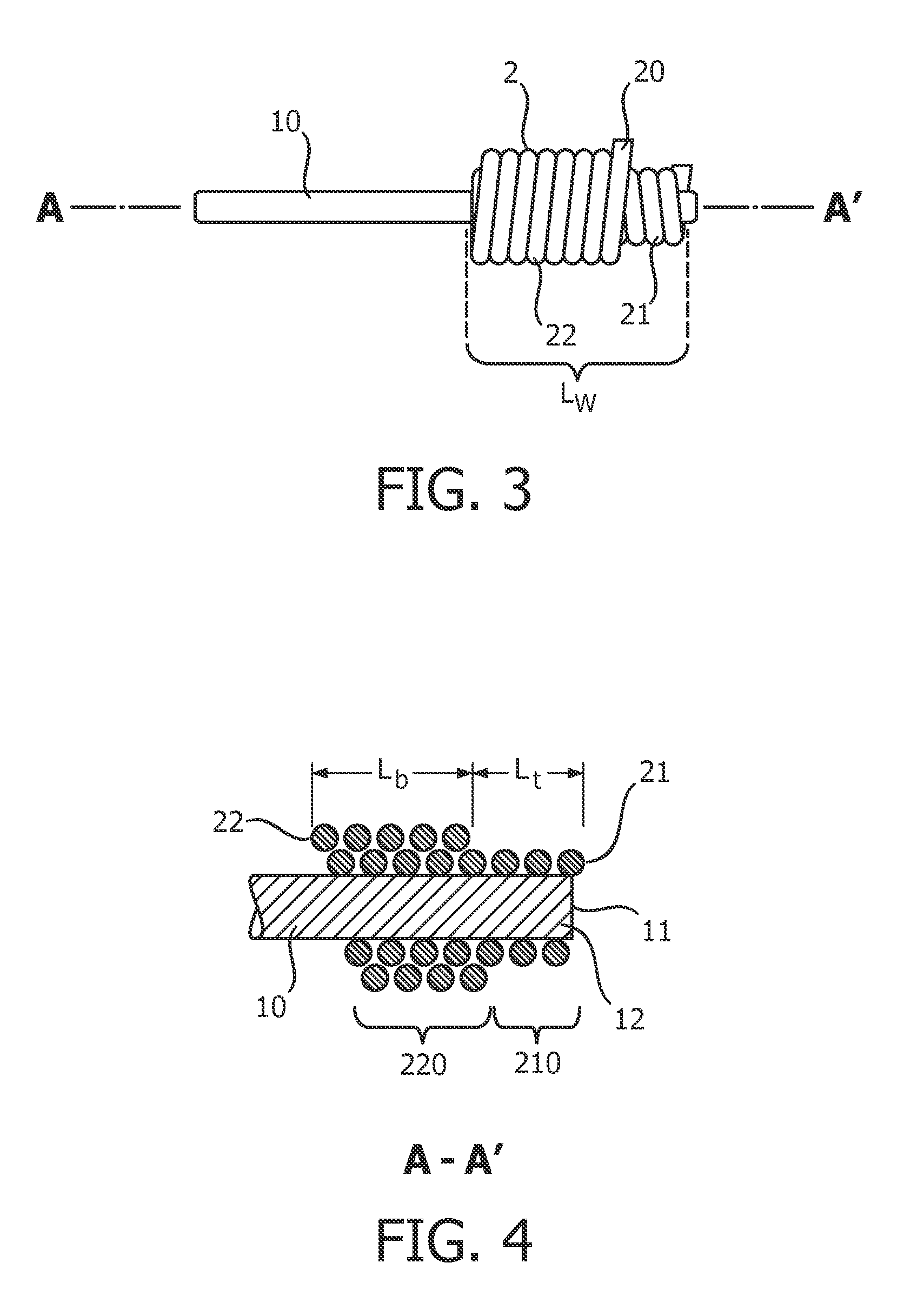
[0017]Preferably, the first coil region comprises a portion of the coil arranged around a tip of the electrode, and the first melting step comprises melting material of the first coil region and material of the electrode tip such that the melted material of the coil in the first coil region coalesces or combines with the melted material of the electrode tip to give the fused portion of the one-piece shell. This fused portion allows the electrode tip to behave in a very favourable manner during operation, since a melting back of the electrode is largely prevented, thus effectively allowing the electrode to maintain its shape over the lifetime of the lamp, without any severe geometrical distortion.
[0020]Any suitable technique of applying heat to melt the coil and electrode material could be used to shape the one-piece shell. However, in a particularly preferred embodiment of the invention, the step of melting material of the coil comprises directing a beam of laser light at the coil. In this way, energy can be deposited very precisely, to precisely chosen depths in the material of the coil and / or electrode, in order to melt only desired regions of the coil and / or electrode.
[0023]In the fused portion of the one-piece shell, the coil winding structure is no longer present, so that energy can only be radiated away from the electrode from the outer surface of the shell. Therefore, in a particularly preferred embodiment of the invention, the coil winding comprises an inner coil layer and at least one outer coil layer, and the mantle portion of the one-piece shell comprises a re-solidified outer coil layer. In this way, an inner coil layer underneath the mantle can still act to draw heat away from the electrode body and therefore also from the tip of the electrode, while the outer mantle ensures an improved mechanical performance under thermal load. Of course, the coil winding can comprises two, three or even more inner coil layers.
[0026]The luminous flux and the luminance of a discharge arc established between the front faces of two opposing electrodes will depend on the distance between the front faces. Therefore, in a particularly preferred embodiment of the invention, a separation between a front face of the first electrode and a front face of the second electrode can be in a range between 0.7 mm and 1.6 mm, depending on the optical characteristics of the lighting assembly or lighting system in which the lamp is to be used. Generally, in a gas-discharge lamp according to the invention, the electrodes can be positioned closer to each other, for example with an electrode separation of about 80% of the electrode separation in a comparable prior art lamp, so that a shorter arc with a correspondingly higher luminance can be established. The collection efficiency of the gas-discharge lamp according to the invention, i.e. the ratio of luminous flux collected through an aperture to the total luminous flux of the lamp can be favourably increased in the region of about 10 percent compared to a gas-discharge lamp with prior art electrodes.

Problems solved by technology

The electrodes in gas-discharge lamps such as those used for digital projection lighting (DPL) become very hot during operation of the lamp.
The temperature at the tips of the electrodes can easily reach 3700 K. At such high temperatures, the thermal load on an electrode is extreme, and the tip of the electrode can melt back and significantly alter the shape of the electrode.
Since the cost of an optical panel is related to its size, the relatively large electrode separation of prior art electrodes in UHP lamps is also a cost factor in the manufacture of optical panels for projection systems using those lamps.
The evolution towards smaller optical panels makes a smaller electrode separation desirable, so that the effects of burn-back exhibited by prior art electrodes can be a serious drawback.
However, such large electrodes are correspondingly heavy and would require a complete re-design, including adjustments to driving scheme parameters of a lamp driver.
However, even for such a coil-and-rod electrode, the unavoidably high temperature at the tip of the electrode will melt the electrode tip.
High power DPL lamps suffer from a specific type of electrode failure, since it may happen that parts of the coil ‘open’ or even break during lamp operation as a result of the high thermal load.
While coil breakage occurs quickly and effectively terminates the lamp lifetime, coil opening can significantly shorten the lamp lifetime, so that both of these negative developments are highly undesirable.
Furthermore, coil ‘opening’ means that the coil unwinds slowly under the thermal load, with a corresponding negative effect on the electrode's thermal characteristics.
For example, an electrode with an ‘opened’ coil may be associated with an increase of lamp operating voltage, since the coil no longer fulfils its function and the electrode is subject to a greater thermal load.
Also, the high thermal load in the electrode results in the very undesirable burn-back of the electrode front faces.

Method used


Image

  • Method of manufacturing an electrode for a gas discharge lamp
  • Method of manufacturing an electrode for a gas discharge lamp
  • Method of manufacturing an electrode for a gas discharge lamp

Examples


Embodiment Construction

[0035]FIG. 1 shows a prior art UHP lamp 5, comprising a quartz glass burner 4 enclosing a discharge chamber 40. A pair of electrodes 50 is disposed in a co-linear arrangement in the discharge chamber 40 such that the front faces of the electrodes 50 are separated by a distance D. Each electrode 50 is connected to a molybdenum foil 41 in a pinch region of the lamp 5, and this foil 41 is in turn connected to an external electrode lead 42, so that a voltage can be applied across the electrodes 50. Each electrode 50 comprises a coil winding 51, which is partially melted in a fused region 52 at the tip of the electrode 50 to combine with the material of the electrode 50. This prior art electrode design is shown in FIG. 2 in more detail. The fused region 52 of the electrode 50 protects the electrode tip region from serious deformation during operation of the lamp 5.

[0036]FIG. 3 shows an electrode component prior to melting, and shows an electrode shaft 10 and a winding 2, made by arrangin...


PUM

PropertyMeasurementUnit
diameteraaaaaaaaaa
temperaturesaaaaaaaaaa

Abstract

The invention describes a method of manufacturing an electrode (1) for a gas-discharge lamp, which method comprises forming an electrode shaft (10); forming a coil (2) over a winding length (L W); arranging the coil (2) on the electrode shaft (10); and melting material of the coil (2) such that, when the melted coil material has re-solidified, the solidified material (30,31) comprises a one-piece shell (3), which one-piece shell (3) comprises a fused portion (30) over a fraction (L T) of the winding length (L W) and a mantle portion (31) over a remainder (L B) of the winding length (L W). The invention further describes an electrode (1) for a gas-discharge lamp, which electrode (1) comprises an electrode shaft (10); a coil (2) arranged on the electrode shaft (10) over a winding length (L W); and a one-piece shell (2) comprising re-solidified material of the coil (2), which one-piece shell (3) comprises a fused portion (30) over a fraction (L T) of the winding length (L W) and a mantle portion (31) over a remainder (L B) of the winding length (L W). The invention also describes a gas-discharge lamp (6) comprising a burner (4) enclosing a discharge vessel (40), a first electrode (1) and a second electrode (1), wherein the electrodes (1) are arranged to protrude into the dis-charge vessel (40) from opposite sides of the discharge vessel (40), wherein at least one of the electrodes (1) comprises an electrode (1) according to the invention.

Description

FIELD OF THE INVENTION[0001]The invention describes a method of manufacturing an electrode for a gas-discharge lamp, an electrode for a gas-discharge lamp, and a gas-discharge lamp.BACKGROUND OF THE INVENTION[0002]The electrodes in gas-discharge lamps such as those used for digital projection lighting (DPL) become very hot during operation of the lamp. In particular, operating conditions in ultra high-pressure (UHP) gas-discharge lamps are such that temperatures of 1200 K are easily reached in the coolest area of the lamp, namely the pinch area. The temperature at the tips of the electrodes can easily reach 3700 K. At such high temperatures, the thermal load on an electrode is extreme, and the tip of the electrode can melt back and significantly alter the shape of the electrode. This is known as electrode burn-back. When both electrodes are shortened by burn-back, the separation between the front faces of the electrodes lengthens, as does the discharge arc, so that the luminance of ...

Claims


Application Information

Patent Timeline
Patent Type & Authority Patents(United States)
IPC IPC(8): H01J61/073H01J9/02H01J61/86
CPCH01J61/0732H01J9/02H01J61/86
Inventor POORTMANS, STIJNVAN DAELE, BENNYVAN BYLEN, KURT MARCEL FRIEDA
Owner KONINK PHILIPS ELECTRONICS NV
Why Eureka
Try Eureka