Terminal plate set and electric connector including the same

a technology of terminal plates and electric connectors, which is applied in the direction of coupling contact members, coupling device connections, electrical devices, etc., can solve the problems of reducing the heat dissipation efficiency of electric connectors, the inability to easily dissipate the heat generated by signal terminal plates and grounding terminal plates of electric connectors, and the greater power loss of electric connectors. to achieve the effect of improving the heat dissipation efficiency

Active Publication Date: 2015-06-09
ALL BEST PRECISION TECH
View PDF28 Cites 26 Cited by
  • Summary
  • Abstract
  • Description
  • Claims
  • Application Information

AI Technical Summary

Benefits of technology

[0004]In view of the drawbacks of the prior art, the inventor of the present invention based on years of experience in the related industry to conduct extensive researches and experiments, and finally developed a terminal plate set and an electric connector including the terminal plate set, in hope of adjusting the impedance of the signal terminal plate and the grounding terminal plate to the best range and improving the heat dissipation efficiency of the terminal plate set and the electric connector.
[0014]The terminal plate set and the electric connector of the present invention can adjust the impedance of the signal terminal plate and the grounding terminal plate to the best range and improve the heat dissipation efficiency of the terminal plate set and the electric connector.

Problems solved by technology

However, the signal terminal plates and the grounding terminal plates of the electric connector are arranged closely with each other, so that the effective dielectric coefficients of the signal terminal plates and the grounding terminal plates of the electric connector become relatively higher, and the electric connector has a greater power loss.
Since the signal terminal plates and the grounding terminal plates of the electric connector are arranged closely with each other, air cannot flow easily between the signal terminal plates and the grounding terminal plates of the electric connector, and the heat generated by the signal terminal plates and the grounding terminal plates of the electric connector cannot be dissipated easily, and the heat dissipation efficiency of the electric connector is lowered.

Method used


Image

  • Terminal plate set and electric connector including the same
  • Terminal plate set and electric connector including the same
  • Terminal plate set and electric connector including the same

Examples


Embodiment Construction

[0027]The objects, characteristics and effects of the present invention will become apparent with the detailed description of the preferred embodiments and the illustration of related drawings as follows.

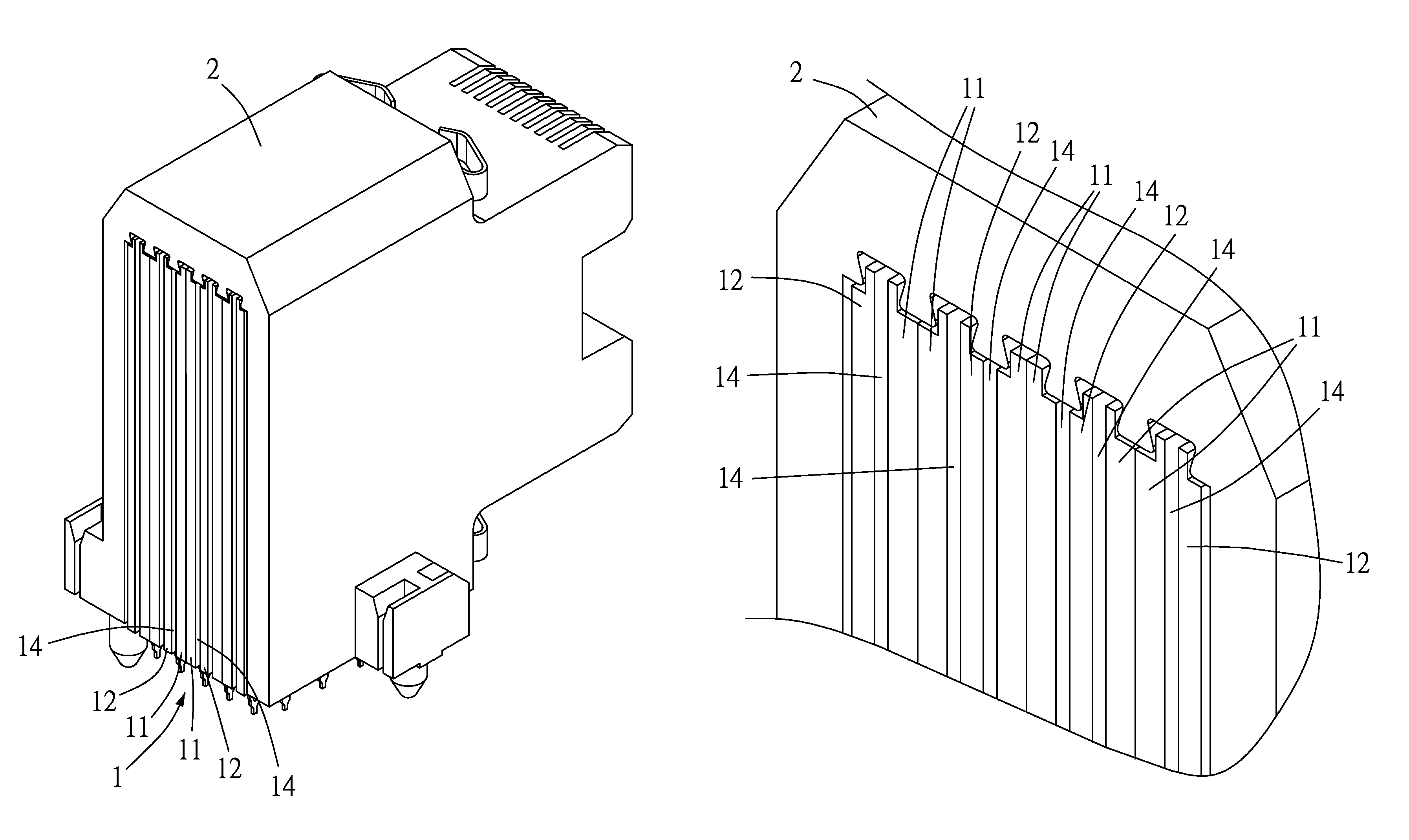
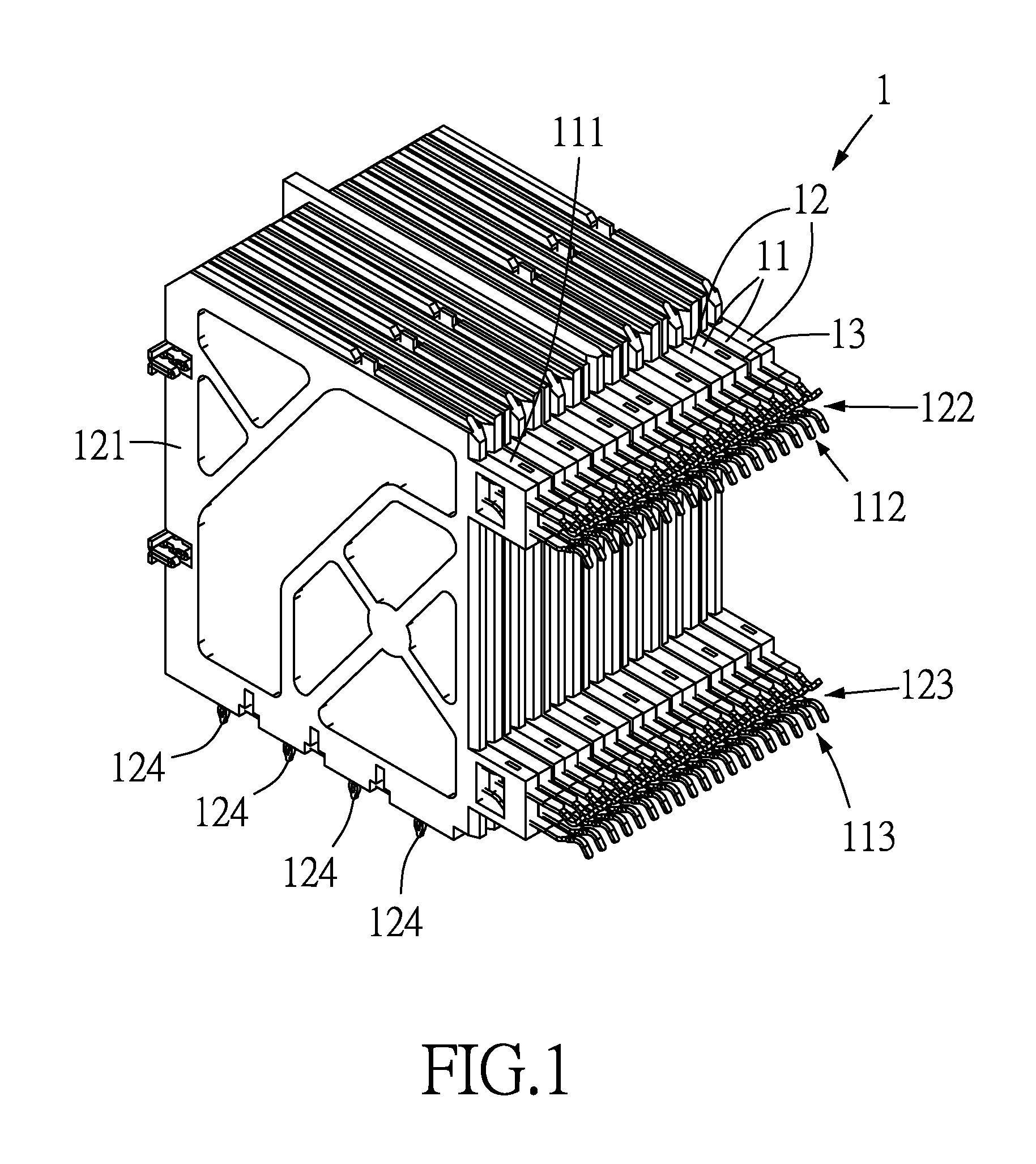
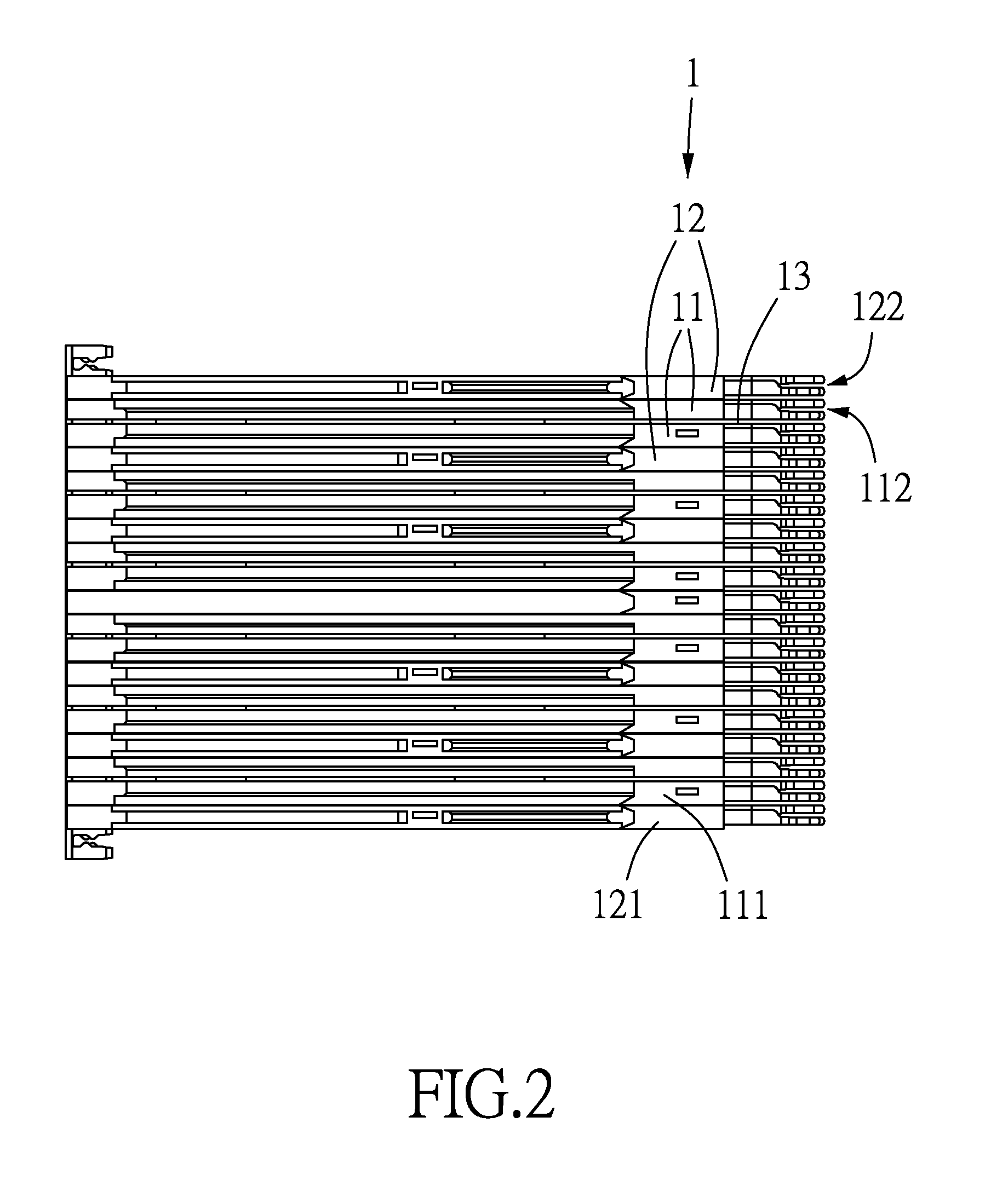
[0028]With reference to FIGS. 1 to 7 for the schematic views of the first to sixth preferred embodiment of the present invention, and a schematic view of a spacer plate in accordance with the present invention respectively, a first mode of the invention comprises a terminal plate set 1 or a plurality of terminal plate sets 1 arranged parallel to one another. The terminal plate set 1 comprises two signal terminal plates 11 and two grounding terminal plates 12 as shown in FIG. 1, and the terminal plates 11, 12 have a conductive terminal (not shown in the figure) and a covering plate 111, 121 respectively, and the covering plates 111, 121 are covered onto the conductive terminals to prevent the conductive terminals from being short circuited by touching with each other and provide an e...


PUM


Abstract

A terminal plate set and an electric connector including the terminal plate set are disclosed. The terminal plate set includes two signal terminal plates and two grounding terminal plates, and the signal terminal plates are parallel to each other and disposed between the grounding terminal plates. A partition channel is formed between the grounding terminal plates, between the signal terminal plates, between the signal terminal plate and the grounding terminal plate, or between the terminal plates. The electric connector includes the terminal plate set and a front body, and the terminal plate set is installed at the front body, and a front convection hole is formed on a plug side of the front body. The impedance of the signal terminal plates and the grounding terminal plates can be adjusted within the best range to improve the heat dissipation efficiency of the terminal plate set and the electric connector.

Description

FIELD OF THE INVENTION[0001]The present invention relates to a terminal plate set and an electric connector including the terminal plate set, in particular to the terminal plate set and the electric connector capable of adjusting the impedance of a signal terminal plate and a grounding terminal plate to the best range and improving the heat dissipation efficiency of the terminal plate set and the electric connector.BACKGROUND OF THE INVENTION[0002]In general, a computer and an electronic device come with various kinds of electric connectors for connecting the computer and the electronic device. The electric connector generally has two signal terminal plates installed between two grounding terminal plates. However, the signal terminal plates and the grounding terminal plates of the electric connector are arranged closely with each other, so that the effective dielectric coefficients of the signal terminal plates and the grounding terminal plates of the electric connector become relat...

Claims


Application Information

Patent Timeline
Patent Type & Authority Patents(United States)
IPC IPC(8): H01R9/24H01R13/02
CPCH01R9/24H01R13/02H01R12/724H01R13/6586
Inventor YANG, HAVEN
Owner ALL BEST PRECISION TECH
Why Eureka
Try Eureka