Solar thermal collectors

a solar thermal power plant and collector technology, applied in the direction of heat collector mounting/support, lighting and heating equipment, instruments, etc., can solve the problems of high cost of a dish, high cost, and inability to easily mount mirrors directly to the space fram

Active Publication Date: 2015-06-16
SUNRISE CSP PTY
View PDF36 Cites 1 Cited by
  • Summary
  • Abstract
  • Description
  • Claims
  • Application Information

AI Technical Summary

Problems solved by technology

The problem with prior art space frame designs is that the individual components are relatively expensive to manufacture and so the cost of a dish is, generally, high.
This may be acceptable for a one off design, such as a prototype or a radio telescope dish, but the cost is too high for use in a solar thermal power plant that may require hundreds or thousands of individual collector dishes.
A further problem is that mirrors cannot easily be mounted directly to the space frame and must be mounted via their own individual support structure.
This increases the mass and cost of the overall structure.

Method used


Image

  • Solar thermal collectors
  • Solar thermal collectors
  • Solar thermal collectors

Examples


Embodiment Construction

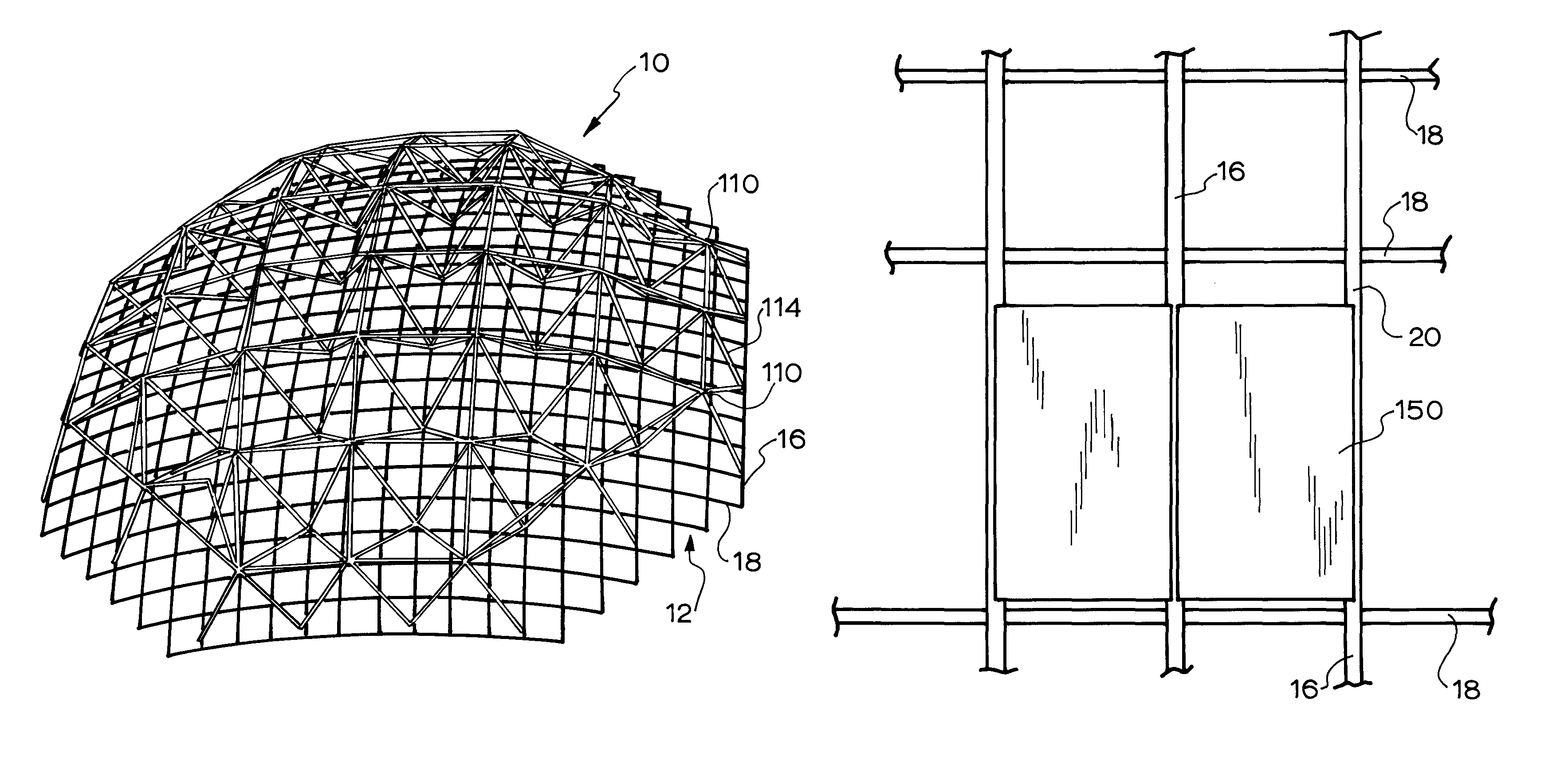
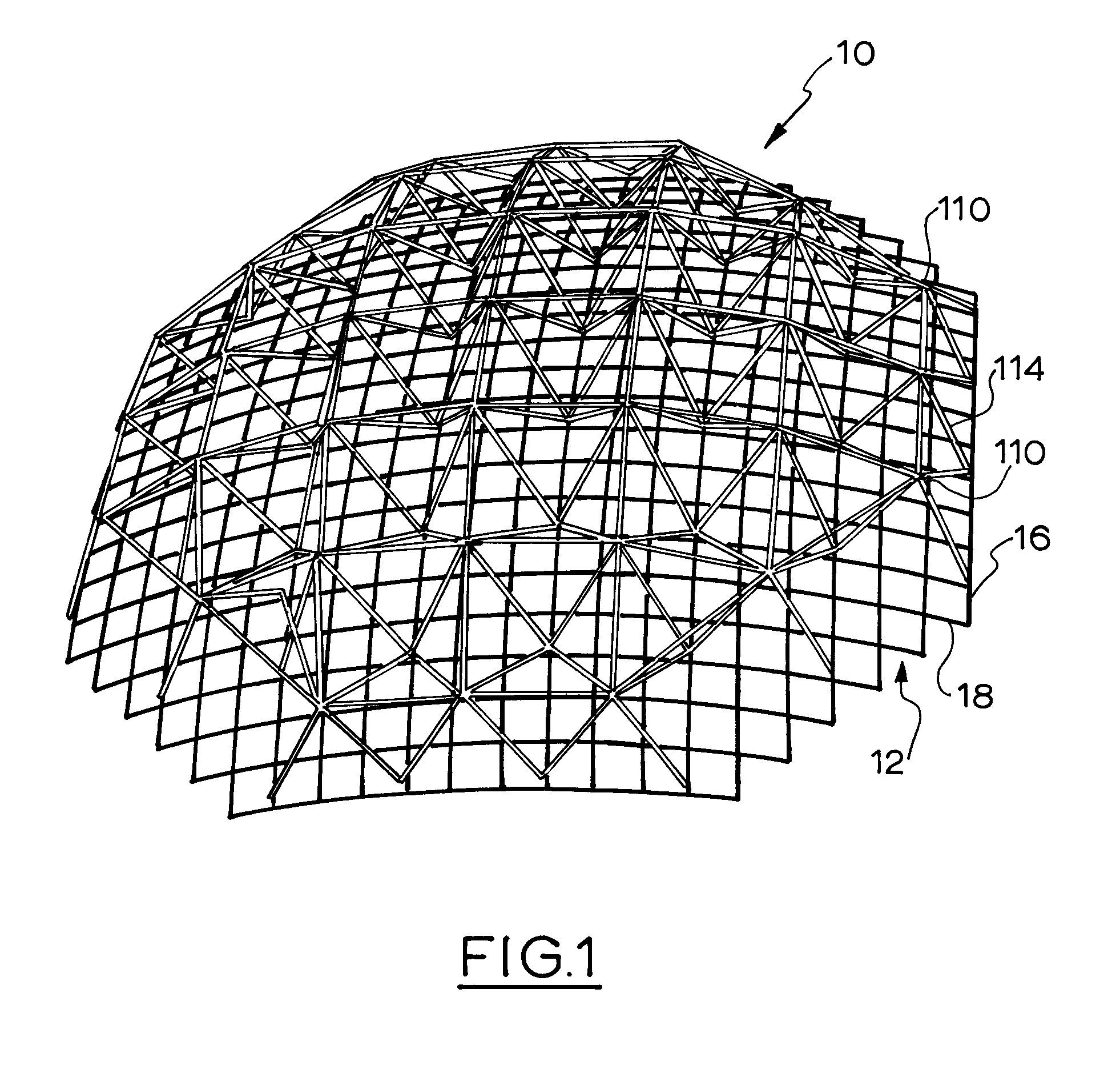
[0077]Referring to FIGS. 1 to 15 there is shown the structure of a parabolic dish 10, for use with mirrors, according to an embodiment of the invention and a jig for its construction. For clarity the mirrors are not shown in these drawings but are shown in FIGS. 17 and 18.

[0078]The dish structure may be divided into a front structure 12 and a rear structure 14.

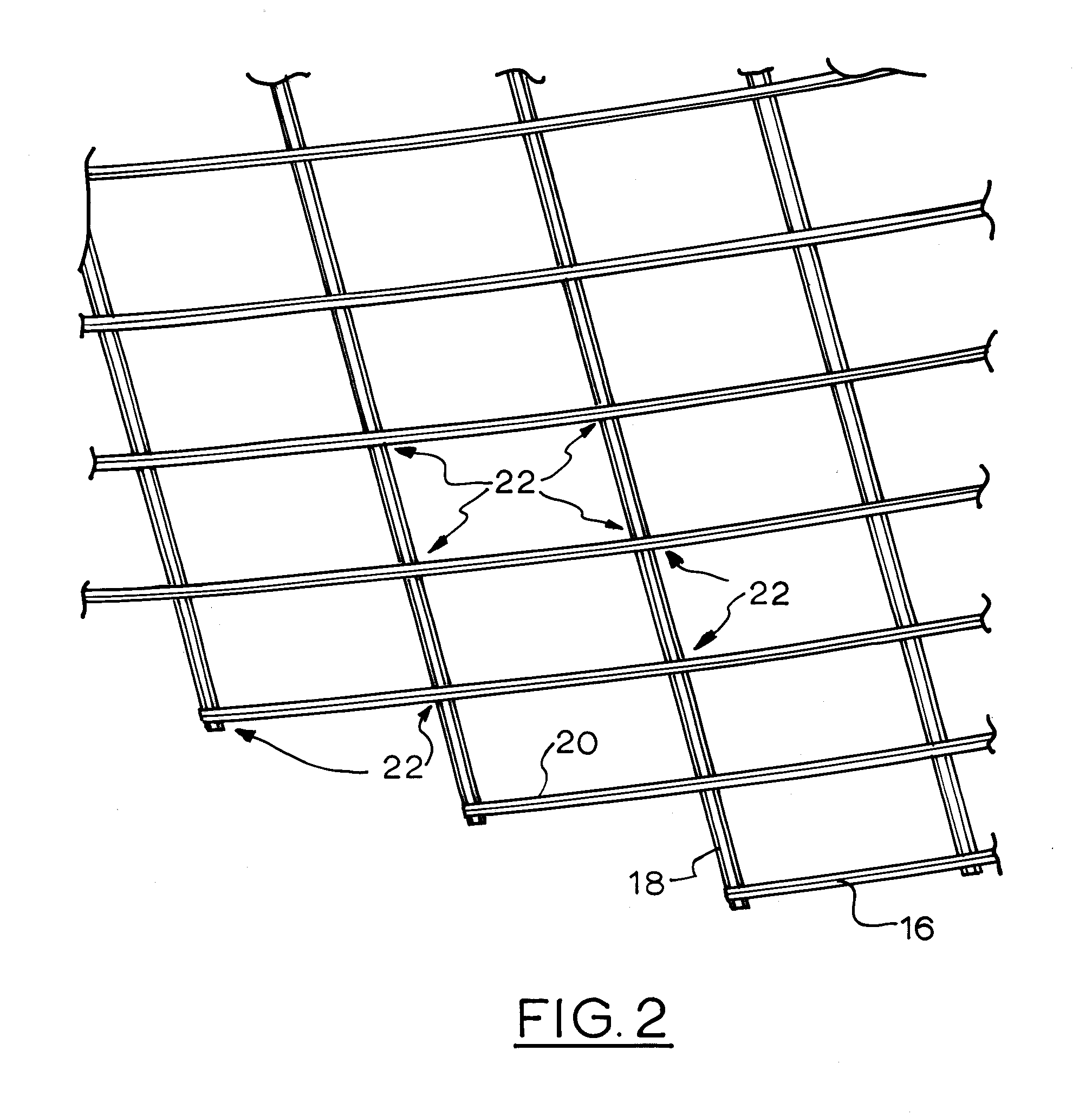
[0079]The front structure 12 is formed of a series of elongate front beams 16 that are arranged side by side and spaced apart. A series of elongate rear beams 18 extend generally transversely across the rear of the front beams 16 and are also spaced apart and arranged side by side. In this embodiment the front face 20 of each beam provides a single mounting area upon which mirrors may be mounted.

[0080]The front beams 16 are curved so the mounting area or areas of each front beam 16 follows a virtual curved surface along its length. In this case the front surface 20 follows the virtual curved surface along its length. The front...


PUM


Abstract

A dish structure (10) has a virtual front surface, the front surface having a periphery, and a plurality of spaced apart non overlapping elongate front beams (16), each of which extends between two points on the periphery. Each front beam (16) has at least one mounting area (20) for receiving a reflective panel (150), the at least one mounting area (20) conforming substantially to the virtual front surface in the longitudinal direction of the front beam (16).

Description

FIELD OF INVENTION[0001]This invention relates to dish like structures and more particularly to dish like structures for parabolic mirror type solar thermal collectors. However, the invention is not limited to parabolic mirror type solar thermal collectors.BACKGROUND[0002]Sunlight is a source of “renewable” energy that may be captured for human use using various techniques. One method of concentration is to use a number of large parabolic dishes, each of which that supports a mirrored surface that concentrates the light onto its own heat collector fixed relative to the mirrored surface. Each dish is manipulated so that the sunlight stays focused on the collection point as the Earth moves during the day.[0003]Each dish usually has a radius in the order of 10 to 30 meters. The mirrored surface needs to follow a desired parabolic surfaces to a relatively high degree of accuracy so that the focal area is relatively small and the efficiency high.[0004]Prior art techniques of forming the ...

Claims


Application Information

Patent Timeline
Patent Type & Authority Patents(United States)
IPC IPC(8): F24J2/12F24J2/52F24J2/54F24S23/71
CPCF24J2/12F24J2/5203F24J2/54Y02E10/42Y02E10/47F24S23/71F24S25/30F24S30/40Y02E10/40
Inventor LOVEGROVE, KEITH MALCOLMCOVENTRY, JOSEPH SYDNEYBRUNSWICK, ROBERTBURGESS, GREGORY JOHNJOE, WIE SHUENPRESTON, JESSICA NEETAPYE, JOHN DOWNING
Owner SUNRISE CSP PTY
Why Eureka
Try Eureka