Remote sensing using coherent sonic wave photoacoustic detection and methods

a technology of photoacoustic detection and remote sensing, applied in the field of remote sensing using coherent sonic wave photoacoustic detection and methods, can solve problems such as the degree of accuracy and the measurement of parameters

Inactive Publication Date: 2015-06-16
UNITED STATES OF AMERICA THE AS REPRESENTED BY THE SEC OF THE ARMY
View PDF0 Cites 4 Cited by
  • Summary
  • Abstract
  • Description
  • Claims
  • Application Information

AI Technical Summary

Problems solved by technology

However, such claims are premised on assumptions that that may, or may not be accurate, and these assumptions greatly affect LIDAR derived results, e.g., most LIDAR predictions involve an inverse process that requires important information about aerosol size distribution, shape, and composition, which is rarely known with any degree of accuracy.
The main limitation with the LIDAR approach is that it can only measure a parameter called optical backscatter which is a complex function of many phenomena.
However, to make use of this type of measurement, practitioners must make important assumptions as mentioned above because atmospheric backscatter is a complex function of both scattering and absorption.

Method used


Image

  • Remote sensing using coherent sonic wave photoacoustic detection and methods
  • Remote sensing using coherent sonic wave photoacoustic detection and methods
  • Remote sensing using coherent sonic wave photoacoustic detection and methods

Examples


Embodiment Construction

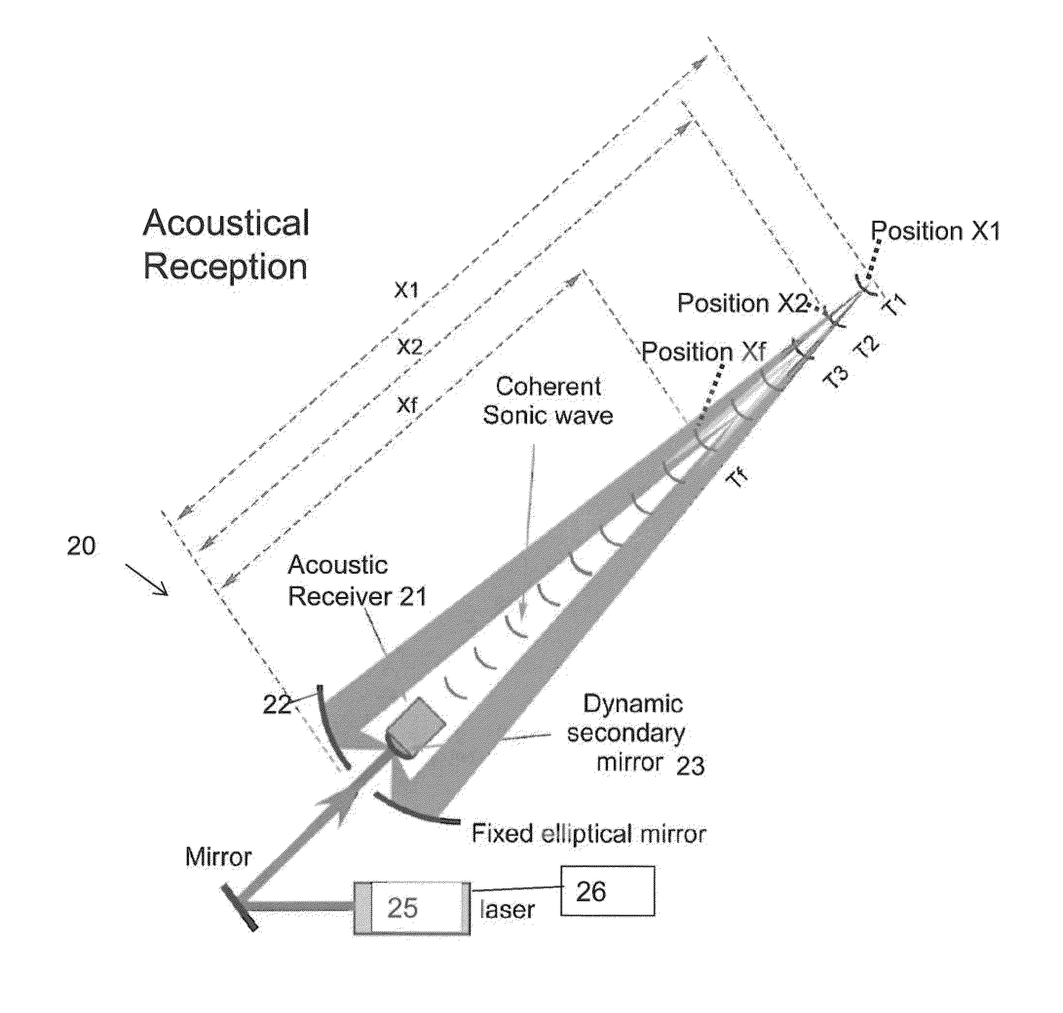
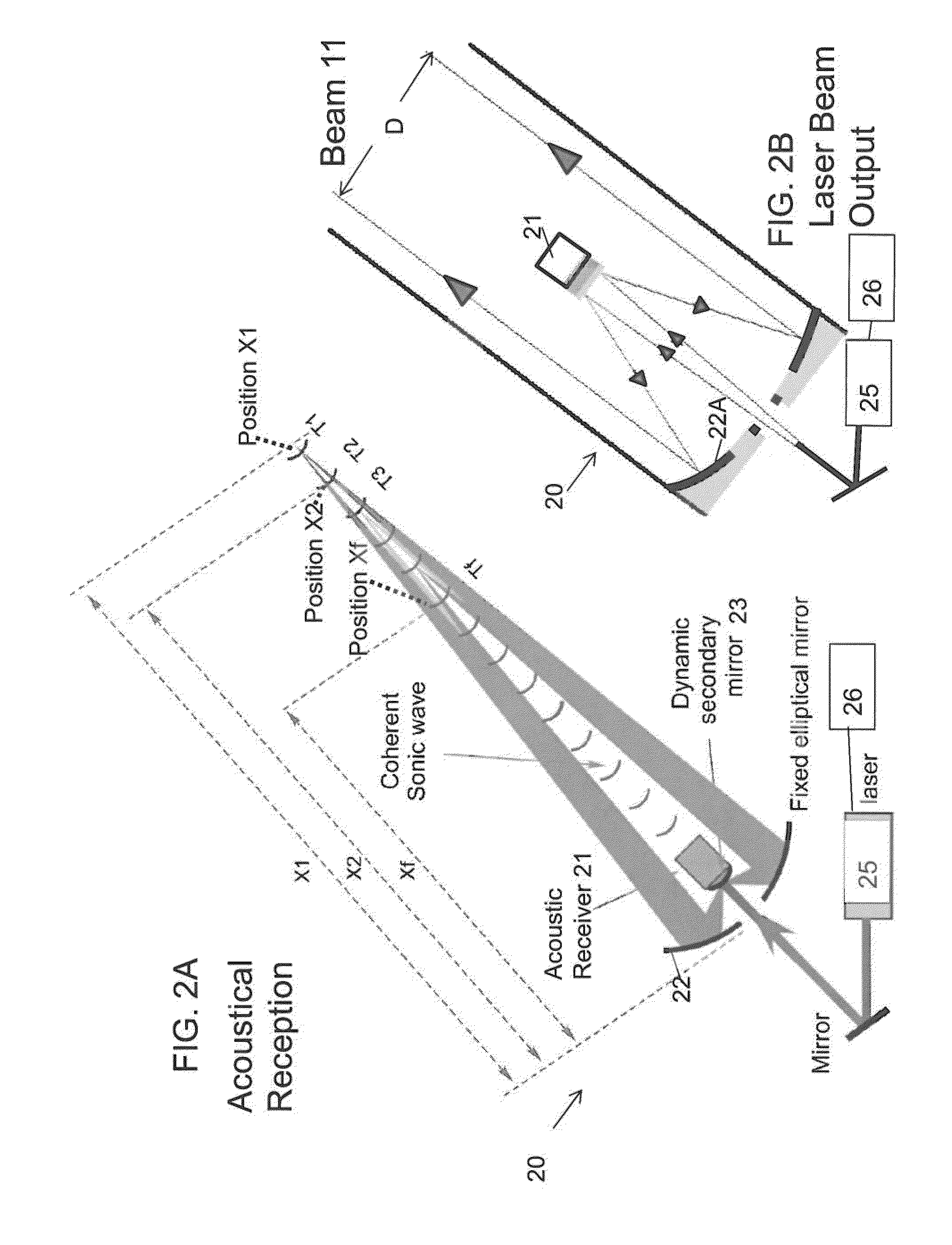
[0022]The embodiments of the invention and the various features and advantageous details thereof are explained more fully with reference to the non-limiting embodiments that are illustrated in the accompanying drawings and detailed in the following description. It should be noted that the features illustrated in the drawings are not necessarily drawn to scale. Descriptions of well-known components and processing techniques are omitted so as to not unnecessarily obscure the embodiments of the invention. The examples used herein are intended merely to facilitate an understanding of ways in which the embodiments of the invention may be practiced and to further enable those of skill in the art to practice the embodiments of the invention. Accordingly, the examples should not be construed as limiting the scope of the embodiments of the invention. Rather, these embodiments are provided so that this disclosure will be thorough and complete, and will fully convey the scope of the invention ...


PUM

PropertyMeasurementUnit
compositionaaaaaaaaaa
physicalaaaaaaaaaa
thermal inhomogeneityaaaaaaaaaa

Abstract

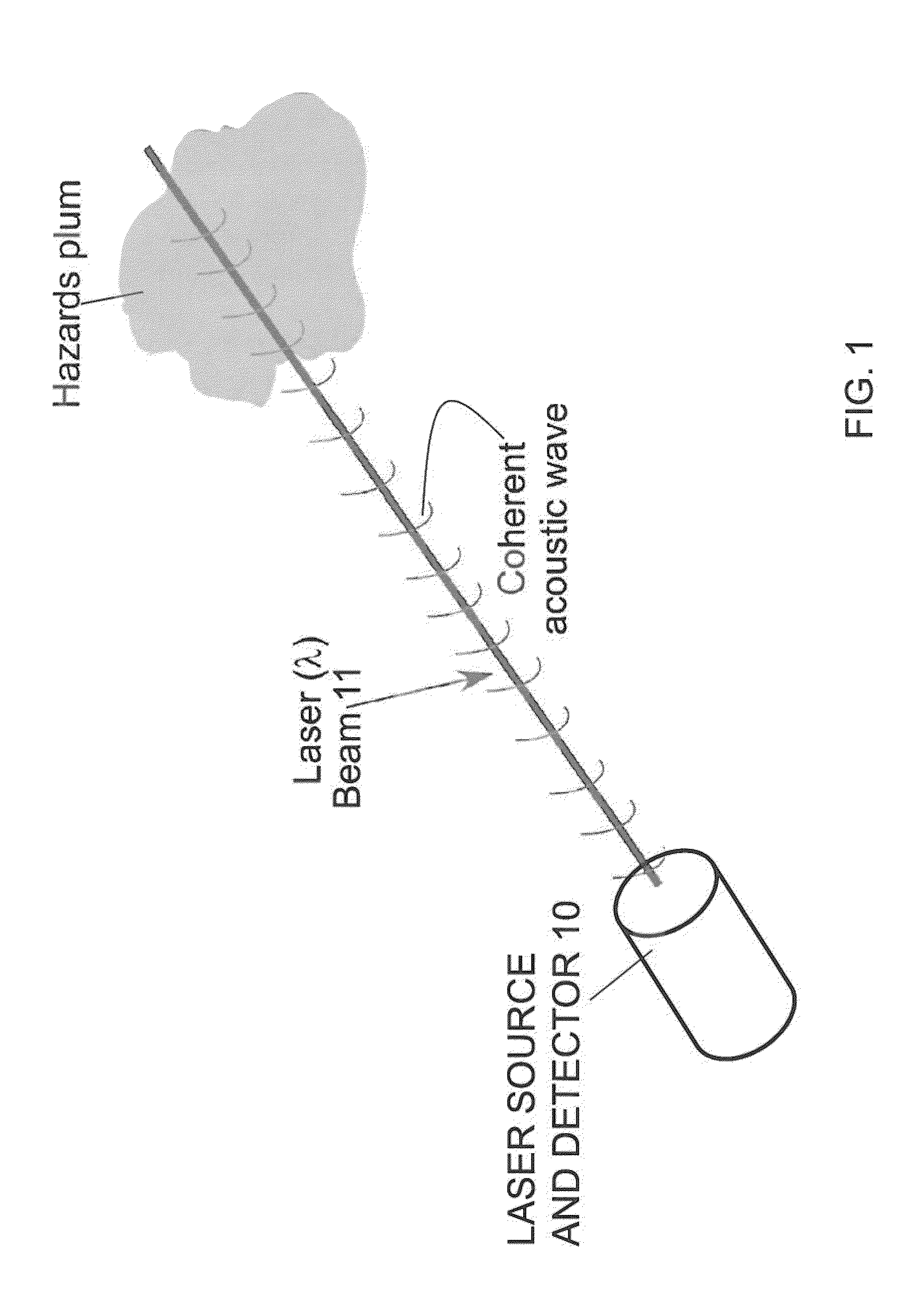
A method and system for detecting composition of a physical space comprising: a laser beam source; an acoustic sensor; a beam focusing mechanism for focusing the laser beam at predetermined points in the physical space to generate a thermal inhomogeneity which results in the propagation of a pressure wave that propagates outward from the predetermined excitation point at a propagation velocity approximating the speed of sound for the particular composition of the media; at least one processor for controlling the timing for the laser beam focusing to generate thermal inhomogeneities; whereby the laser focal point is moved sequentially along the light-of-sight at various excitation points by the beam focusing mechanism approximately at the phase front velocity to define a series of predetermined excitation points and pressure wave propagations such that the series of pressure wave propagations combine to produce a coherent pressure wave detectable by the acoustic sensor.

Description

STATEMENT OF GOVERNMENT INTEREST[0001]The invention described herein may be manufactured, used, and licensed by or for the United States Government without the payment of royalties thereon.BACKGROUND OF THE INVENTION[0002]A body of research has been conducted in which lasers are used to induced phase-change (create a plasma) on solid surfaces and in gases, in order to deduce atomic related spectral information, i.e., laser induced breakdown spectroscopy. Similarly, there is a body of research in which practitioners have used laser illumination to generate acoustic surface waves, in which Fourier analysis is applied to the acoustic signal, in order to measure non-destructively various physical parameters. See for example, A Harata, H Nishimura, T Sawada, “Laser-induced surface acoustic waves and photo-thermal surface gratings generated by crossing two pulsed laser beams”, App. Phys. Let. Vol. 57, (1990) and D Schneider, T Schwarz, H J Scheibe, M Panzner, “Non-destructive evaluation o...

Claims


Application Information

Patent Timeline
Patent Type & Authority Patents(United States)
IPC IPC(8): G01N21/17G01S15/74G01S17/02G01S17/86
CPCG01S17/023G01S15/74G01N21/1702G01S17/86
Inventor GURTON, KRISTAN PETERPAN, YONGLE
Owner UNITED STATES OF AMERICA THE AS REPRESENTED BY THE SEC OF THE ARMY
Why Eureka
Try Eureka