Pneumatic tire

a technology of pneumatic tires and cylinders, which is applied in the field of pneumatic tires, can solve the problems of reducing the rigidity of the block, reducing the driving stability on snow, and reducing on-ice performance, so as to improve on-ice performance, improve on-snow performance, and good balance

Inactive Publication Date: 2015-06-23
THE YOKOHAMA RUBBER CO LTD
View PDF4 Cites 1 Cited by
  • Summary
  • Abstract
  • Description
  • Claims
  • Application Information

AI Technical Summary

Benefits of technology

[0007]An object of the present invention is to provide a pneumatic tire having a good balance between improved in on-ice performance and improved on-snow performance.

Problems solved by technology

However, providing many sipes in each block reduces the block stiffness, and thus, reduces the driving stability on snow.
In some cases, even the on-ice performance is reduced due to collapsing of the blocks.
Accordingly, it is difficult to improve both the on-ice performance and the on-snow performance at the same time.

Method used


Image

  • Pneumatic tire
  • Pneumatic tire
  • Pneumatic tire

Examples


Embodiment Construction

[0030]Selected embodiments will now be explained with reference to the drawings. It will be apparent to those skilled in the art from this disclosure that the following descriptions of the embodiments are provided for illustration only and not for the purpose of limiting the invention as defined by the appended claims and their equivalents.

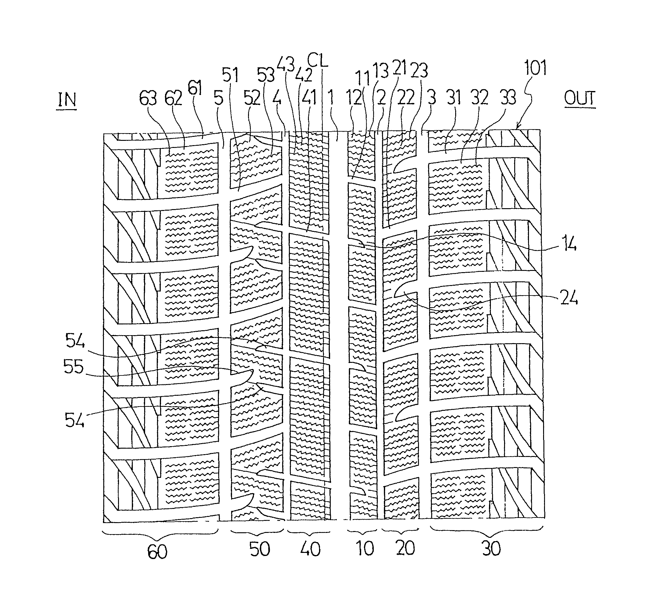
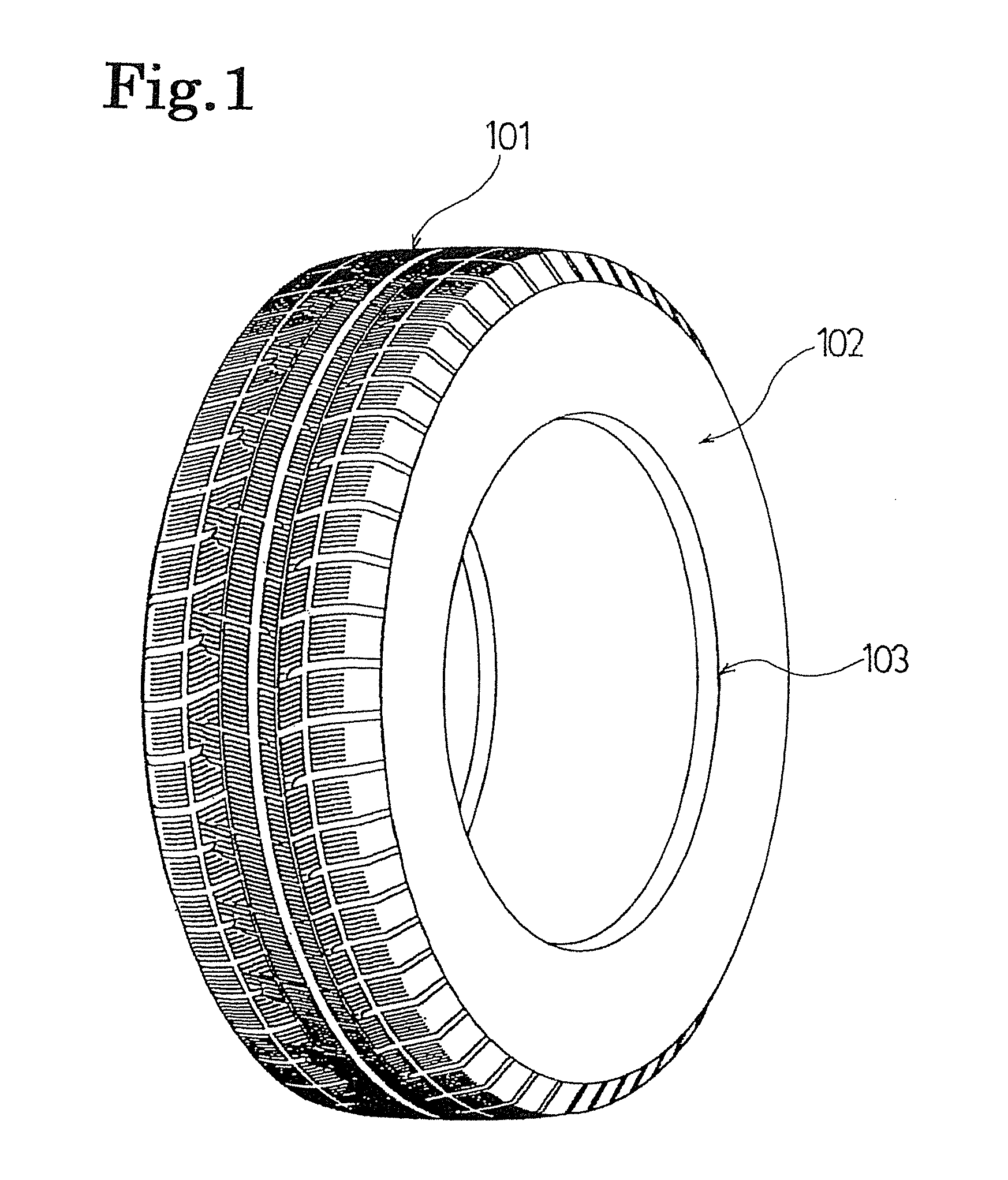
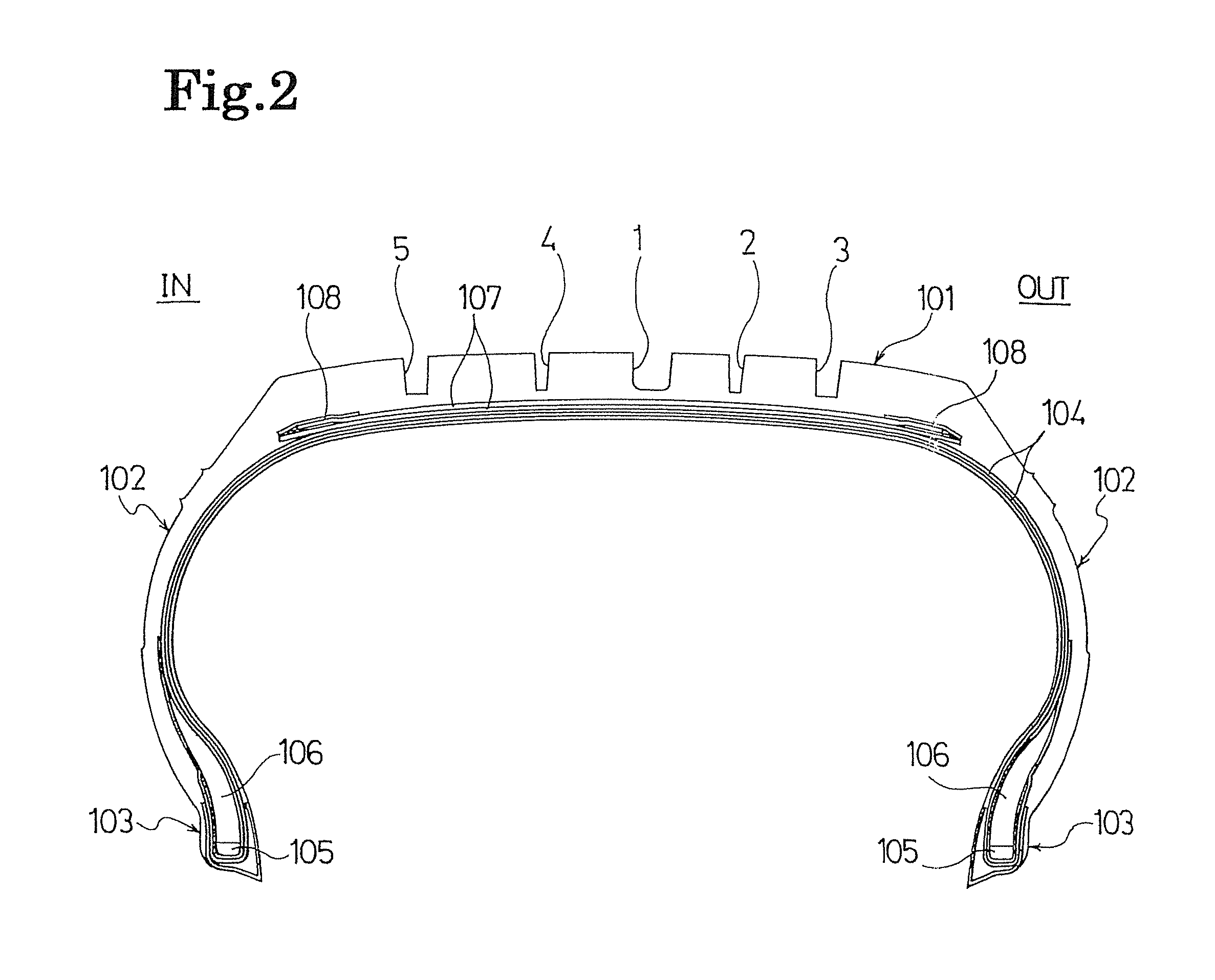
[0031]FIGS. 1 and 2 show a pneumatic tire according to a disclosed embodiment. As shown in FIGS. 1 and 2, the pneumatic tire of the embodiment includes a tread portion 101 extending in a tire circumferential direction and having a ring shape, a pair of sidewall portions 102 respectively disposed on both sides of the tread portion 101, and a pair of bead portions 103 respectively disposed on inner sides of the sidewall portions 102 in a tire radial direction.

[0032]Two carcass layers 104 are installed extending from one bead portion 103 to the other bead portion 103. Each of these carcass layers 104 includes multiple reinforcement cords extending in...


PUM


Abstract

A pneumatic tire has a good balance between on-ice and on-snow performances. The tire includes a tread portion having longitudinal and lateral grooves defining block rows. Each block in the block rows includes sipes. A length of each block in the first and second block rows is not less than 1.5 times and not more than 2.5 times a length of each third block row block. A width of each second block row block is larger than a width of each first block row block. The lateral grooves defining the first and second block row blocks are offset in the tire circumferential direction by not less than 0.2 times and not more than 0.8 times the length of each first block row block. The lateral grooves defining the second and third block row blocks communicate with each other while inclining in the same direction.

Description

CROSS-REFERENCE TO RELATED APPLICATIONS[0001]This application claims priority to Japanese Patent Application No. 2011-106974, filed on May 12, 2011, the entire disclosure of which is hereby incorporated herein by reference.BACKGROUND[0002]1. Field of the Invention[0003]The present invention relates to a pneumatic tire suitable for winter use. More particularly, the present invention relates to a pneumatic tire having improved in on-ice performance and on-snow performance.[0004]2. Background Information[0005]A pneumatic tire for winter use such as a studless tire conventionally has a particular configuration. Specifically, multiple longitudinal grooves extending in a tire circumferential direction and multiple lateral grooves extending in a tire width direction are provided in a tread portion, and these longitudinal and lateral grooves define multiple blocks. Multiple sipes extending in the tire width direction are provided in each of the blocks as described, for example, in Japanese...

Claims


Application Information

Patent Timeline
Patent Type & Authority Patents(United States)
IPC IPC(8): B60C11/03B60C11/11B60C11/12
CPCB60C11/0304B60C11/11B60C11/0306B60C11/1236B60C2011/0381B60C2011/0341B60C2011/0348B60C2011/0372B60C11/03B60C11/032
Inventor NAGAYASU, MASAAKIFURUSAWA, HIROSHI
Owner THE YOKOHAMA RUBBER CO LTD
Why Eureka
Try Eureka