Elastic cantilever beam alignment system for precisely aligning components

a beam alignment and cantilever technology, applied in the direction of superstructure subunits, vehicle components, manufacturing tools, etc., can solve problems such as poor fit, and achieve the effects of eliminating up-down spacing, eliminating rattle, and eliminating cross-car movemen

Active Publication Date: 2015-06-23
GM GLOBAL TECH OPERATIONS LLC
View PDF163 Cites 34 Cited by
  • Summary
  • Abstract
  • Description
  • Claims
  • Application Information

AI Technical Summary

Benefits of technology

[0017]It is to be understood from the foregoing description that as the first component is rotated relative to the second component, the first wedge cam resiliently bends the elastically deformable beam arm, which over-constrained relationship of the first elastic cantilever beam with respect to the first and second alignment walls eliminates cross-car movement of the first and second components so as to precisely align them to each other. Simultaneously, the second wedge cam at the cam sidewall of the cammed aperture acts on the second elastic cantilever beam to cause it to be elastically deformed, which over-constrained relationship therebetween pulls the first and second components together and thereby eliminates up-down spacing therebetween at their joinder, facilitated by the beam boss, if present. Additionally the over-constrained relationships at the fully mated state of the first and second components eliminate rattle and provide stiffened positional constraint between the first and second components. The over-constrained relationships eliminate the variation attributable to the clearances generally needed to assemble mating components in the prior art (i.e., as discussed with respect to FIGS. 1 through 12), eliminates rattle, provides rigidity, and serves to pull the mating components toward each other resulting in precisely aligned mating surfaces.

Problems solved by technology

As a result, there can occur significant positional variation as between the mated first and second components which contributes to the presence of undesirably large and varying gaps and otherwise poor fit therebetween.
In addition, these clearances can inadvertently allow the mated components to move relative to each other, resulting in rattle; necessitating the introduction of a silencing material 68 therebetween, for example as shown at FIG. 12.

Method used


Image

  • Elastic cantilever beam alignment system for precisely aligning components
  • Elastic cantilever beam alignment system for precisely aligning components
  • Elastic cantilever beam alignment system for precisely aligning components

Examples


Embodiment Construction

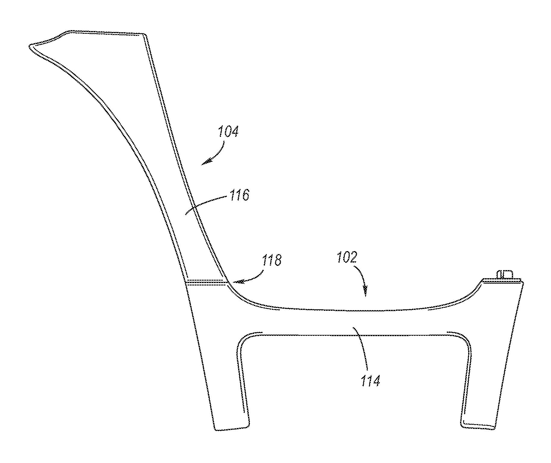
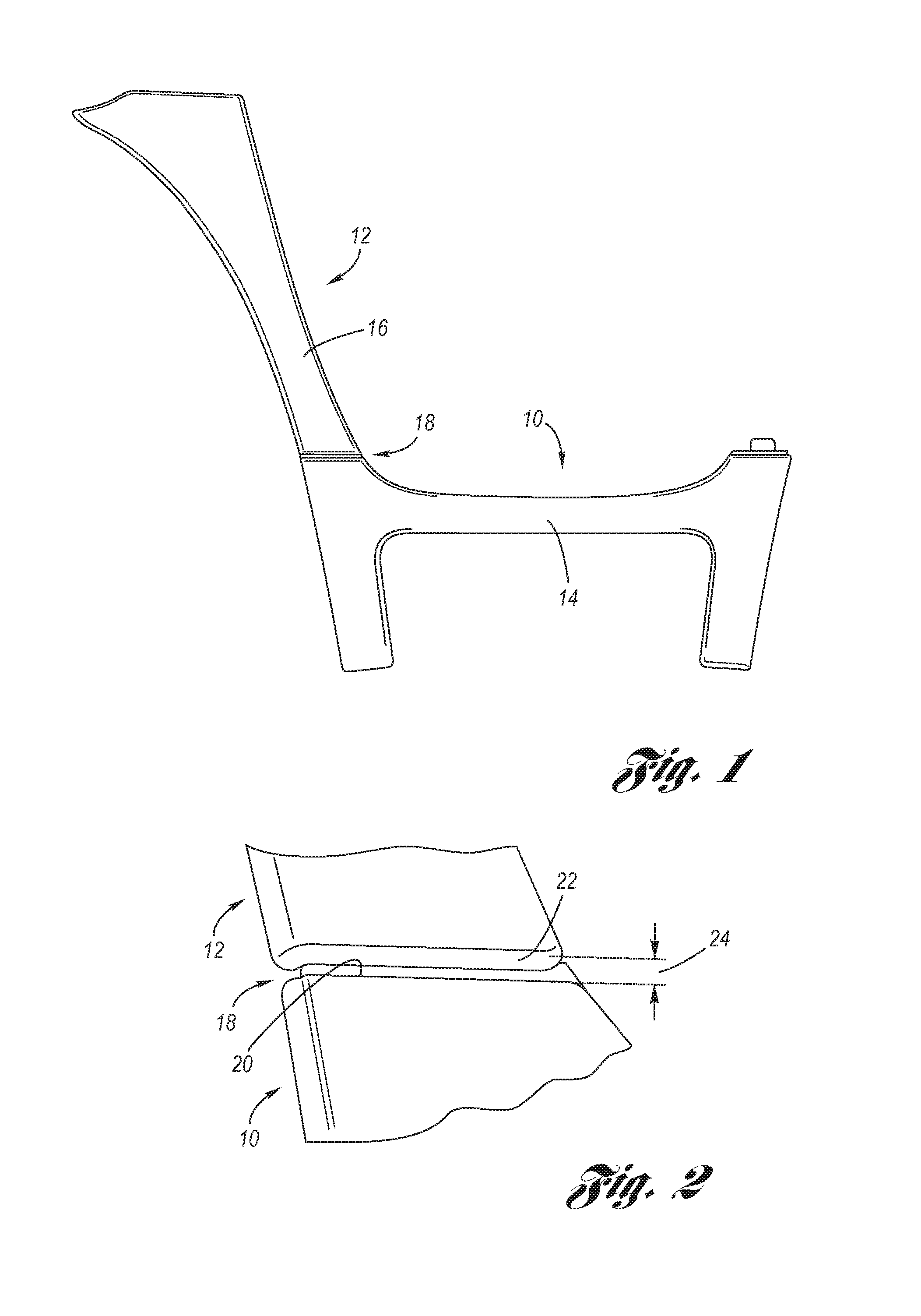
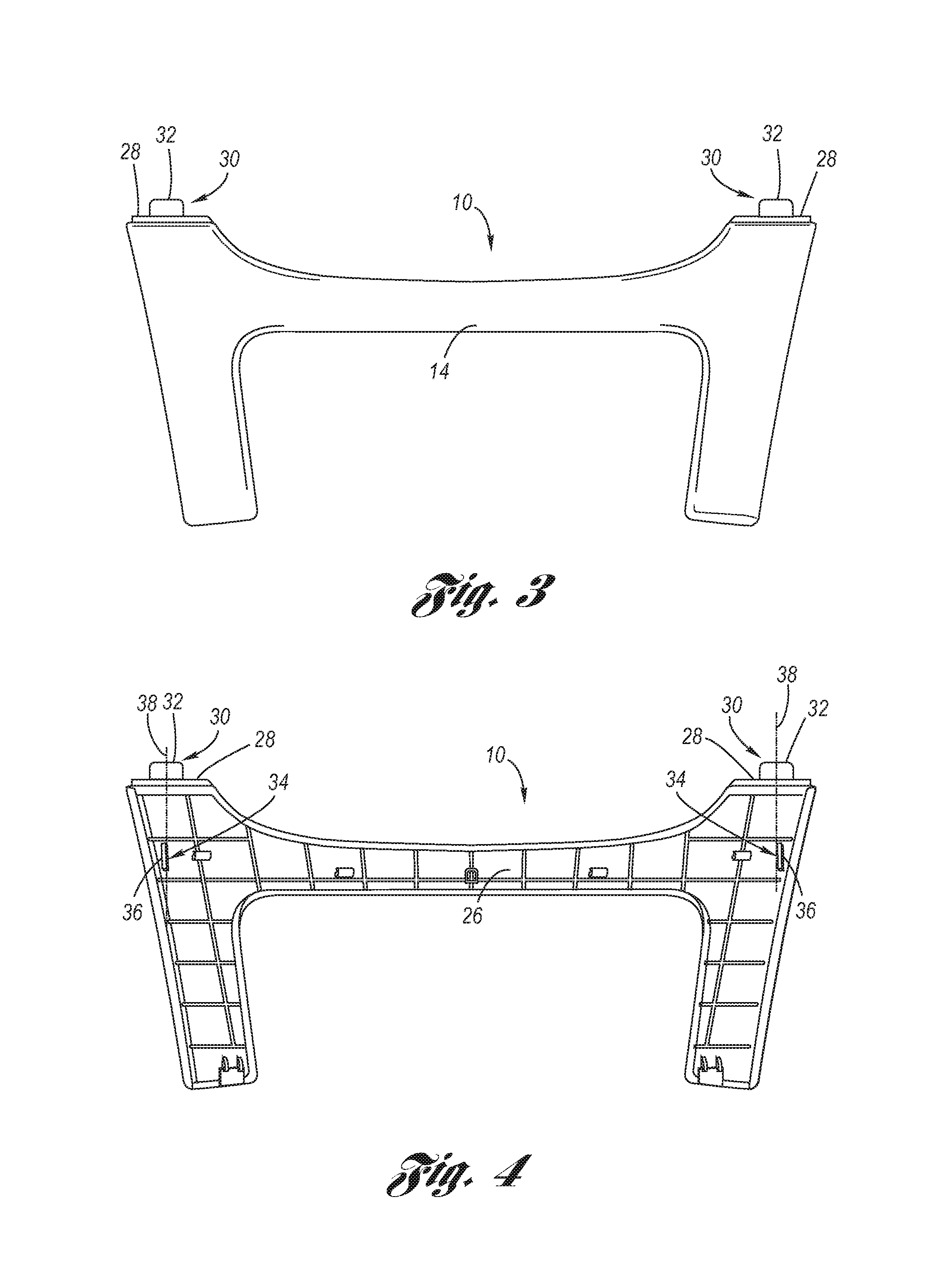
[0050]Referring now to the Drawing, FIGS. 13 through 26 depict various examples of the structure and function of the elastic cantilever beam alignment system 100 according to the present invention for the precise mating of first and second components 102, 104, particularly motor vehicle components, wherein when mating of the first and second components has attained the fully mated state, there is a lack of float (or play) therebetween, and the first and second components have pulled together at the joinder thereof. The lack of float and the pulling together are provided by over-constrained interfacing of first and second male alignment features 106, 108 of the first component with respect to corresponding first and second female alignment features 110, 112 of the second component, wherein a stiffened positional constraint is also thereby provided.

[0051]As depicted at FIG. 13, the first component 102 is mated to the second component 104, wherein the Class A finish side 114, 116 of th...


PUM

PropertyMeasurementUnit
radiusaaaaaaaaaa
radiusaaaaaaaaaa
radiusaaaaaaaaaa

Abstract

An elastic cantilever beam alignment system for the precise mating of first and second components. A first elastic cantilever beam protrudes in parallel from the first component and is elastically over-constrained by two mutually spaced alignment walls of the second component. A second elastic cantilever beam is upstanding in perpendicular relation to the first component and is elastically deformed with respect to a cammed aperture of the second component.

Description

TECHNICAL FIELD[0001]The present invention relates to elastically averaged male and female alignment features which mutually cooperate to precisely align and pull together a pair of components during a mating operation.BACKGROUND OF THE INVENTION[0002]Currently, components which are to be mated together in a manufacturing process are mutually located with respect to each other by 2-way and / or 4-way male location features, typically upstanding bosses, which are received into corresponding female location features, typically apertures in the form of holes or slots. There is a clearance between the male location features and their respective female location features which is predetermined to match anticipated size and positional variation tolerances of the male and female location features as a result of manufacturing (or fabrication) variances. As a result, there can occur significant positional variation as between the mated first and second components which contributes to the presen...

Claims


Application Information

Patent Timeline
Patent Type & Authority Patents(United States)
IPC IPC(8): B25B27/14B62D25/16
CPCB62D25/163Y10T29/53913
Inventor MORRIS, STEVEN E.
Owner GM GLOBAL TECH OPERATIONS LLC
Why Eureka
Try Eureka