Liquid crystal display device

Active Publication Date: 2011-06-30
PANASONIC LIQUID CRYSTAL DISPLAY CO LTD +1
View PDF2 Cites 31 Cited by
  • Summary
  • Abstract
  • Description
  • Claims
  • Application Information

AI Technical Summary

Benefits of technology

[0019]According to the present invention, the partition wall for electrically insulating the electronic component and the LED is not present in the mold. Thus, the overall size of the mold can be reduced by the area of the partition wall. In addition, it is pos

Problems solved by technology

However, the method of arranging the LED, the method of supplying electric current to the LED, and the use efficiency of the light from the LED are problems when trying to reduce the thickness and overall size of the liquid crystal display device.
However, this method has a problem in that it is difficult to obtain sufficient accuracy of the LED arrangement.
Because the setting of the LED flexible wiring substrate and the main flexible wiring substrate at appropriate locations is prioritized, interference may occur between the electronic component mounted on the main flexible wiring substrate, and the LED

Method used


Image

  • Liquid crystal display device
  • Liquid crystal display device
  • Liquid crystal display device

Examples


Example

First Embodiment

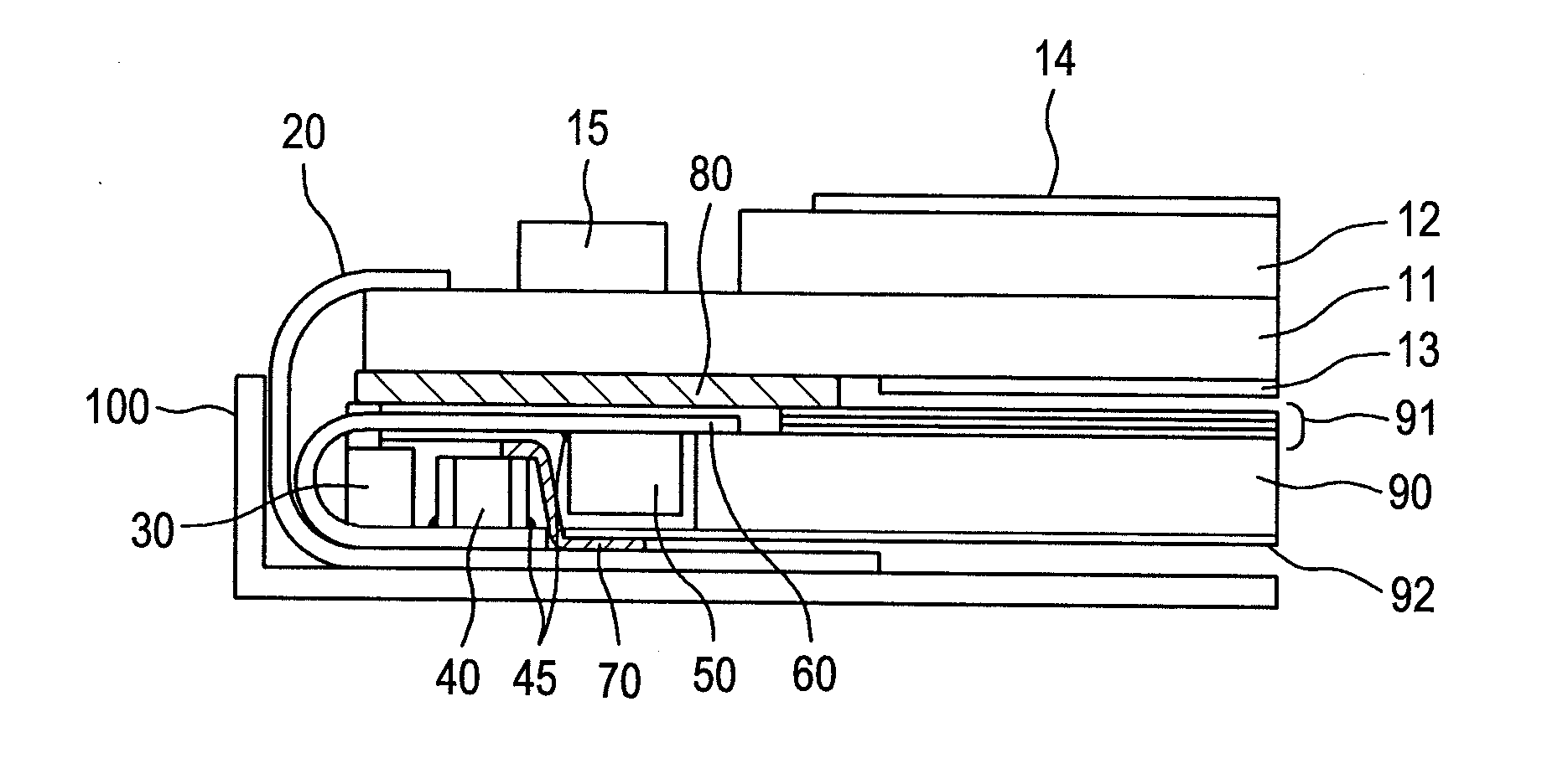
[0043]FIG. 1 is a cross-sectional view of a liquid crystal display device according to a first embodiment of the present invention. FIG. 1 is very different from FIG. 7 showing a conventional example in that the partition wall 31 is not present in the mold 30 in FIG. 1. The absence of the partition wall 31 leads to a risk of short circuit due to the contact between the electronic component 40 and the LED 50. In a first embodiment, a flexible insulating sheet 70 is provided between the LED 50 and the electronic component 40, in order to avoid the risk of short circuit between the LED 50 and the electronic component 40. The insulating sheet 70 covers the electronic component 40 and the side portion of the LED 50, extending to the back side of the reflective sheet 92. The electronic component 40 and the LED 50 are electrically insulated by the insulating sheet 70. As shown in FIG. 1, the resin mold 30, the electronic component 40, the insulating sheet 70, the LED 50, an...

Example

Second Embodiment

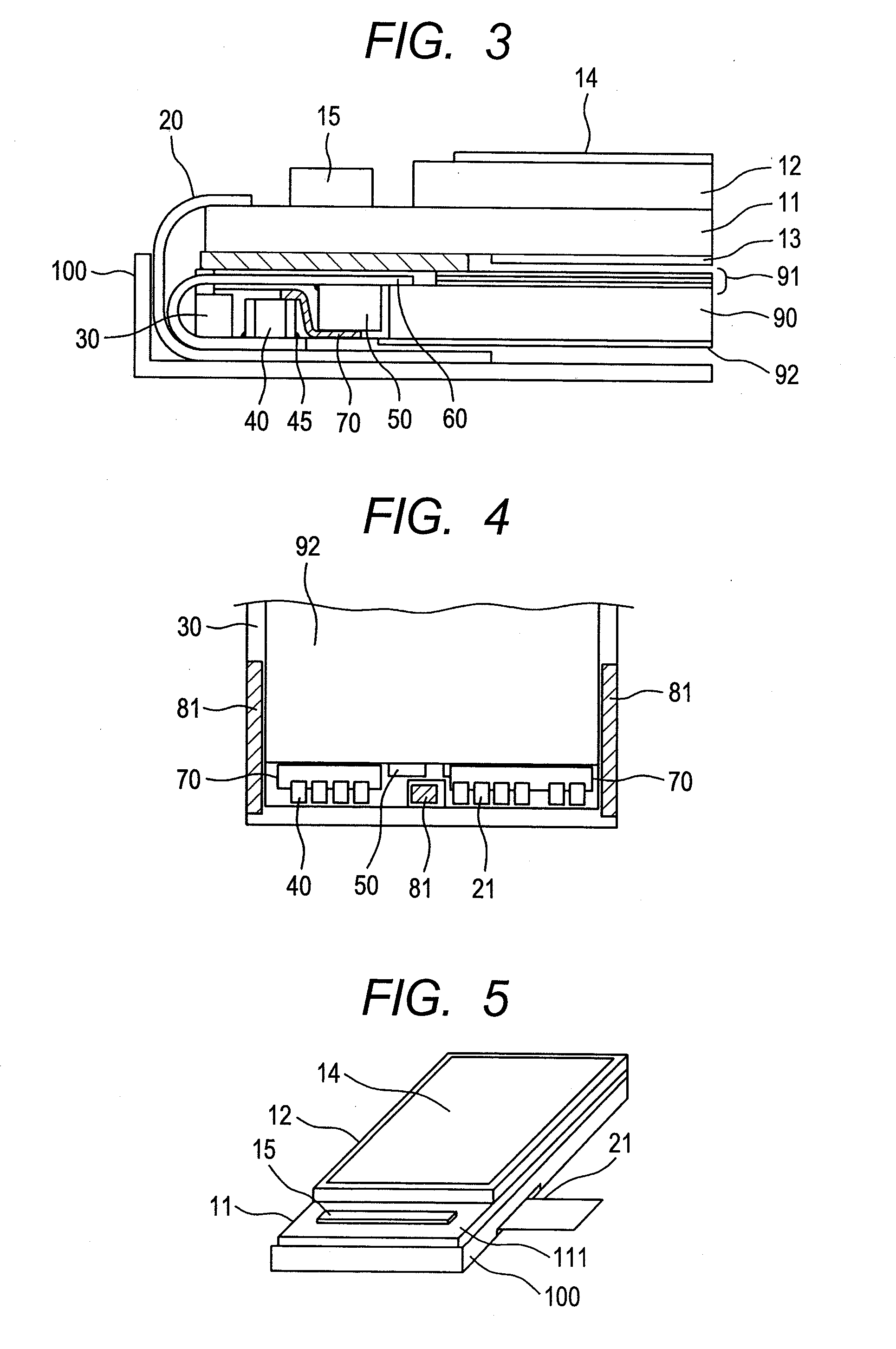
[0055]FIG. 3 is a cross-sectional view of a liquid crystal display device according to a second embodiment. FIG. 3 is different from the first embodiment in that the insulating sheet 70 is not attached to the reflective sheet 92, but is attached to the lower surface of the LEDs 50. The length of the reflective sheet 92 is reduced by this amount. The other configuration shown in FIG. 3 is the same as the configuration shown in FIG. 1. In the second embodiment, the insulating sheet 70 is attached to the lower surface of the LEDs 50, not to the lower surface of the reflective sheet 92. As a result, it is possible to reduce the thickness of the liquid crystal display device by the amount of thickness of the insulating sheet 70.

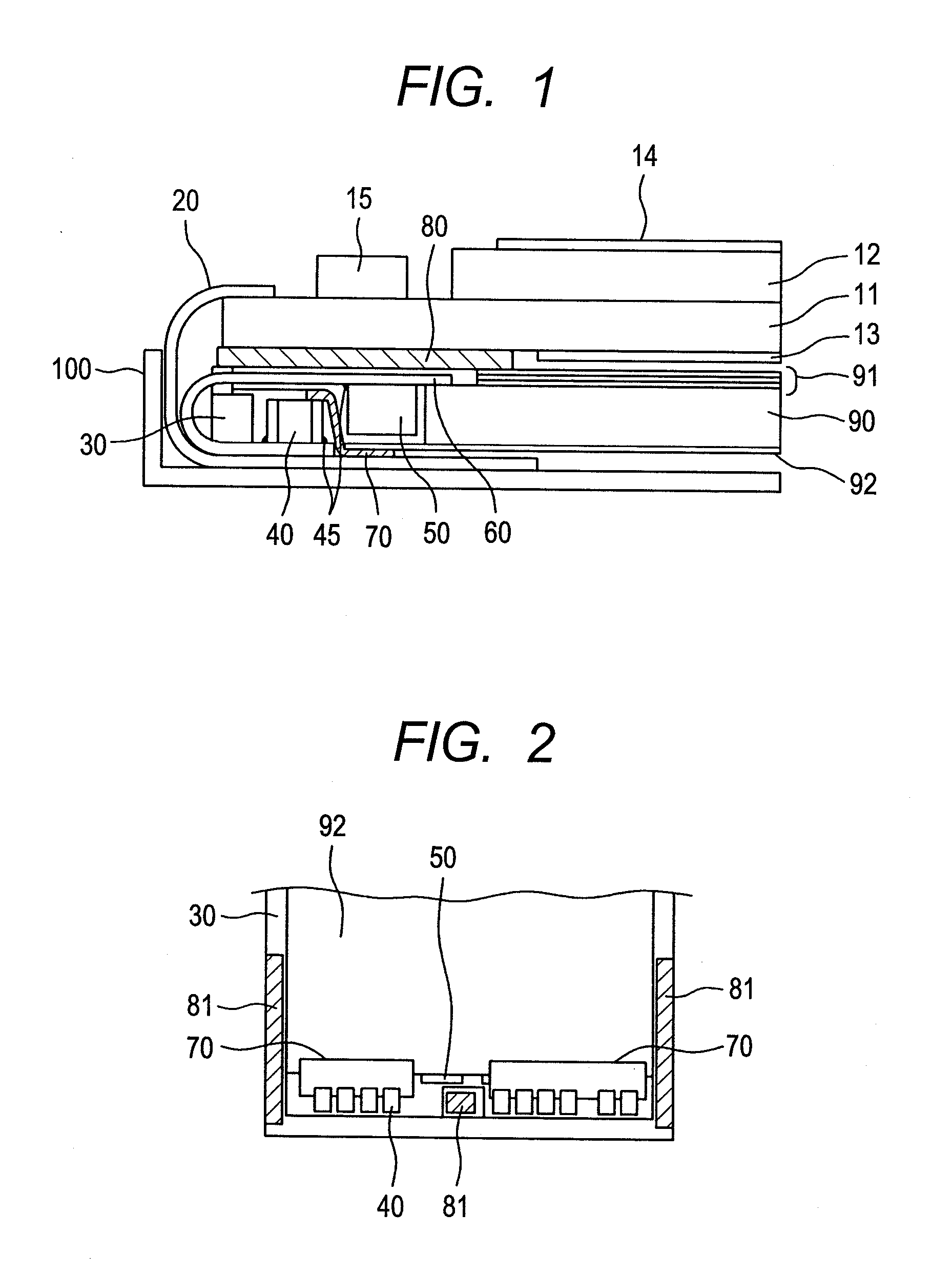
[0056]FIG. 4 is a view from the back side of the liquid crystal display device shown in FIG. 3. In FIG. 4, the metal frame 100, the main flexible wiring substrate 20, and the LED flexible wiring substrate 60 are omitted. The mold-frame adhesive sh...


PUM


Abstract

It is desirable to reduce an overall size of a small liquid crystal display device, while keeping a screen size to a certain value. Thus, there is provided a liquid crystal display device including a liquid crystal display panel on a mold, and a backlight placed in the mold. The backlight includes a light guide panel, an LED provided on a side surface of the liquid guide panel, and other components. A main flexible wiring substrate is attached to the liquid crystal display panel, and extends to a back surface of the mold. The LED is mounted on an LED flexible wiring substrate. An electronic component mounted on the main flexible wiring substrate is placed on the back side of the mold. Then, an insulating sheet is provided between the electronic component and the LED to prevent short circuit between them, instead of using a partition wall for electrical insulation.

Description

CLAIM OF PRIORITY[0001]The present application claims priority from Japanese Patent Application JP 2009-294542 filed on Dec. 25, 2009, the content of which is hereby incorporated by reference into this application.FIELD OF THE INVENTION[0002]The present invention relates to a display device, and more particularly to a configuration for reducing the overall size of a small liquid crystal display device.BACKGROUND OF THE INVENTION[0003]For a liquid crystal display device used in mobile phone and personal digital assistant (PDA), a reduction in thickness is demanded. In addition, there is also a strong demand for making the screen larger while keeping the overall size smaller, namely, making it in the so-called narrow frame form. The small liquid crystal display device uses a light emitting diode (LED) as a light source of a backlight. However, the method of arranging the LED, the method of supplying electric current to the LED, and the use efficiency of the light from the LED are prob...

Claims


Application Information

Patent Timeline
IPC IPC(8): G02F1/1333
CPCG02B6/0068G02B6/0073G02F2001/133314G02F1/133615G02B6/0083G02F1/133314
Inventor MISHIMA, YASUYUKI
Owner PANASONIC LIQUID CRYSTAL DISPLAY CO LTD
Why Eureka
Try Eureka