Electric power management system

a technology of power management system and power meter, which is applied in the direction of electrochemical generators, secondary cell servicing/maintenance, transportation and packaging, etc., can solve the problems of reducing the amount of power output (sold) from the power conditioner to the electric power system of the commercial power source, reducing the amount of power output (sold) from the power conditioner to the power meter, and reducing the time and space required for wiring installation of communications lines. , the effect o

Inactive Publication Date: 2012-07-19
PANASONIC INTELLECTUAL PROPERTY MANAGEMENT CO LTD
View PDF5 Cites 32 Cited by
  • Summary
  • Abstract
  • Description
  • Claims
  • Application Information

AI Technical Summary

Benefits of technology

[0029]With such configuration, the communications between the power meter and the base unit is performed in a wireless manner, the power meter does not require wiring installation for communications, and the time and space required for the wiring installation of a communications line to the power meter are eliminated. When the communications between the power meter and the base unit is performed in a wired manner, communications equipment is simplified and stable communications is ensured. For example, when power line communications is used as the wired communications, the wired communications between the power meter and the base unit can be performed without requiring new wiring installation for communications, thereby saving on wiring in the electric power management system.

Problems solved by technology

For that reason, the power generation pattern thereof is not consistent with the power consumption pattern in houses or other places for many cases.
Further, it is often the case that the generated power amount becomes excessively smaller than the consumed power amount.
Furthermore, the increase in voltage may cause a variation, exceeding an allowable value, in the power of the electric power system of the commercial power source, and reduces the voltage difference between the voltage of the output power of the power conditioner and the voltage of the electric power system of the commercial power source, thereby reducing the amount of power outputted (sold) from the power conditioner to the electric power system of the commercial power source.

Method used


Image

  • Electric power management system
  • Electric power management system
  • Electric power management system

Examples


first embodiment

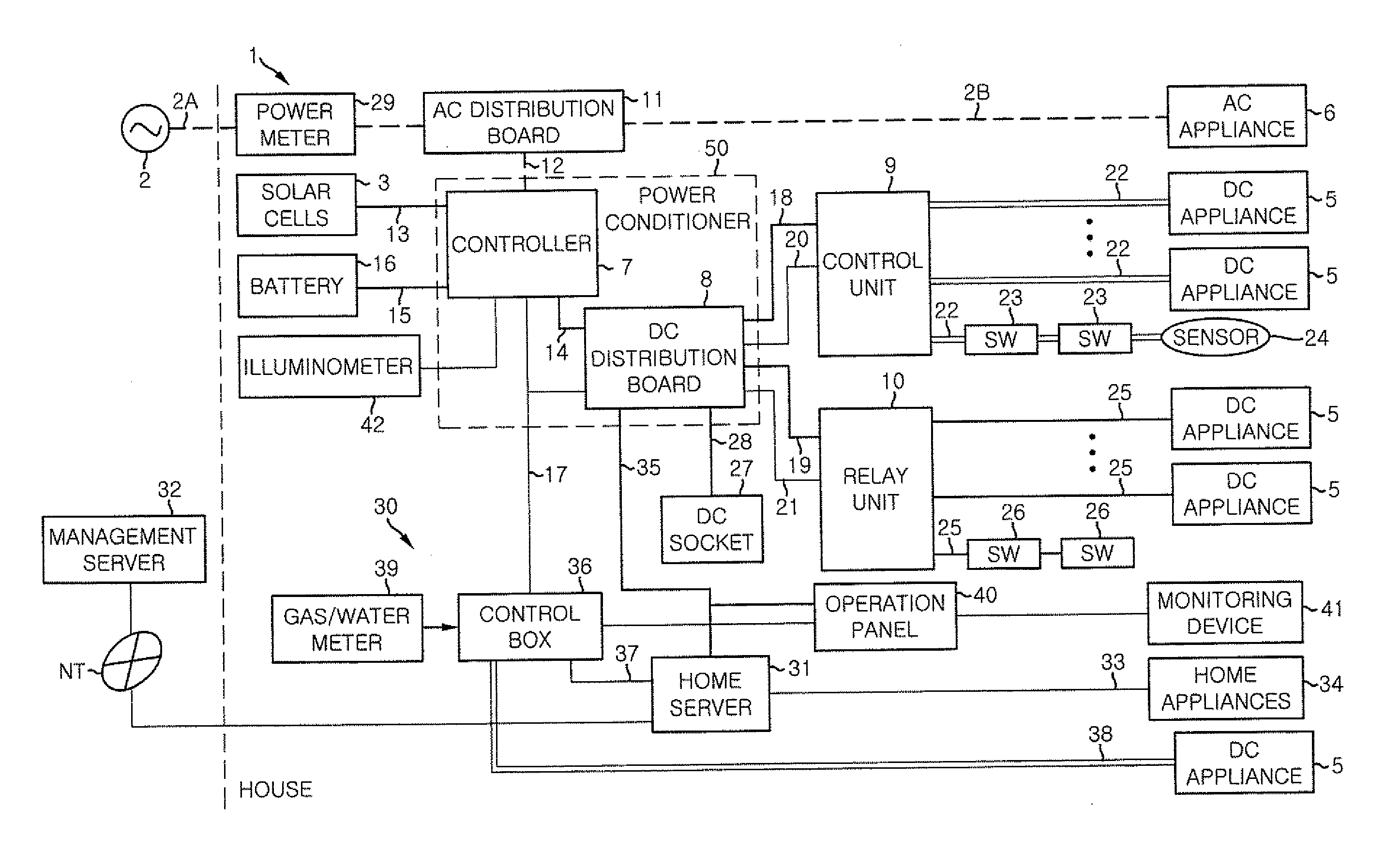
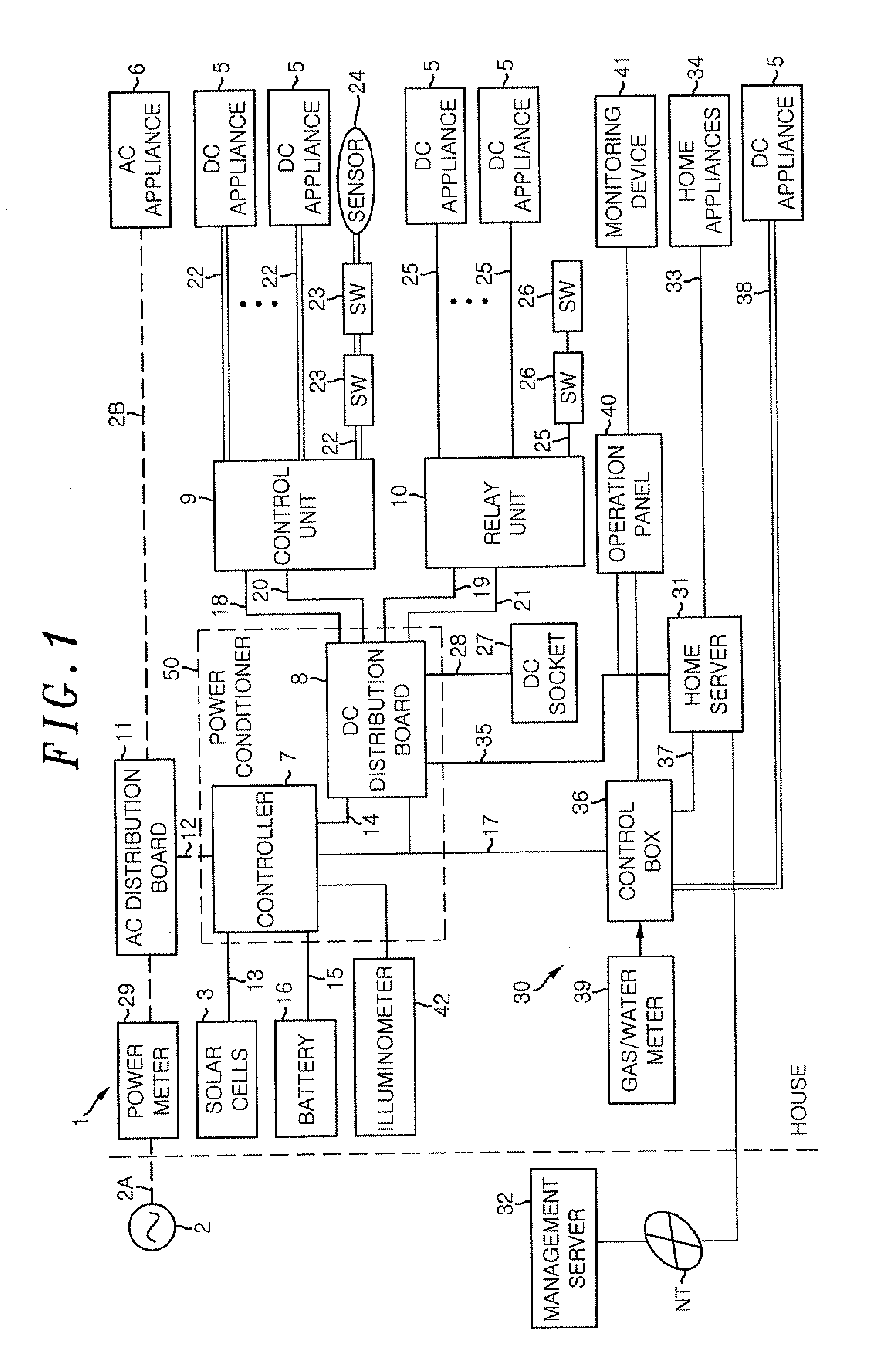
[0046]An electric power management system in accordance with a first embodiment of the present invention will be described in detail. FIG. 1 is a functional block diagram showing a schematic configuration of a power supply system 1 which forms a part of the electric power management system.

[0047]As shown in FIG. 1, a house is provided with the power supply system 1 for supplying an electric power to a variety of home appliances (such as an illuminating device, an air conditioner, an electrical device and an audiovisual device). In the following description, a single house will be taken as an example of the building to which the present invention is applied. However, it is not limited thereto. For example, the present invention may also be applied to building or collective housings such as an office, a shopping arcade and a factory. The power supply system 1 supplies the electric power of a home-use commercial AC source (or a commercial power source) 2 and further supplies the electr...

second embodiment

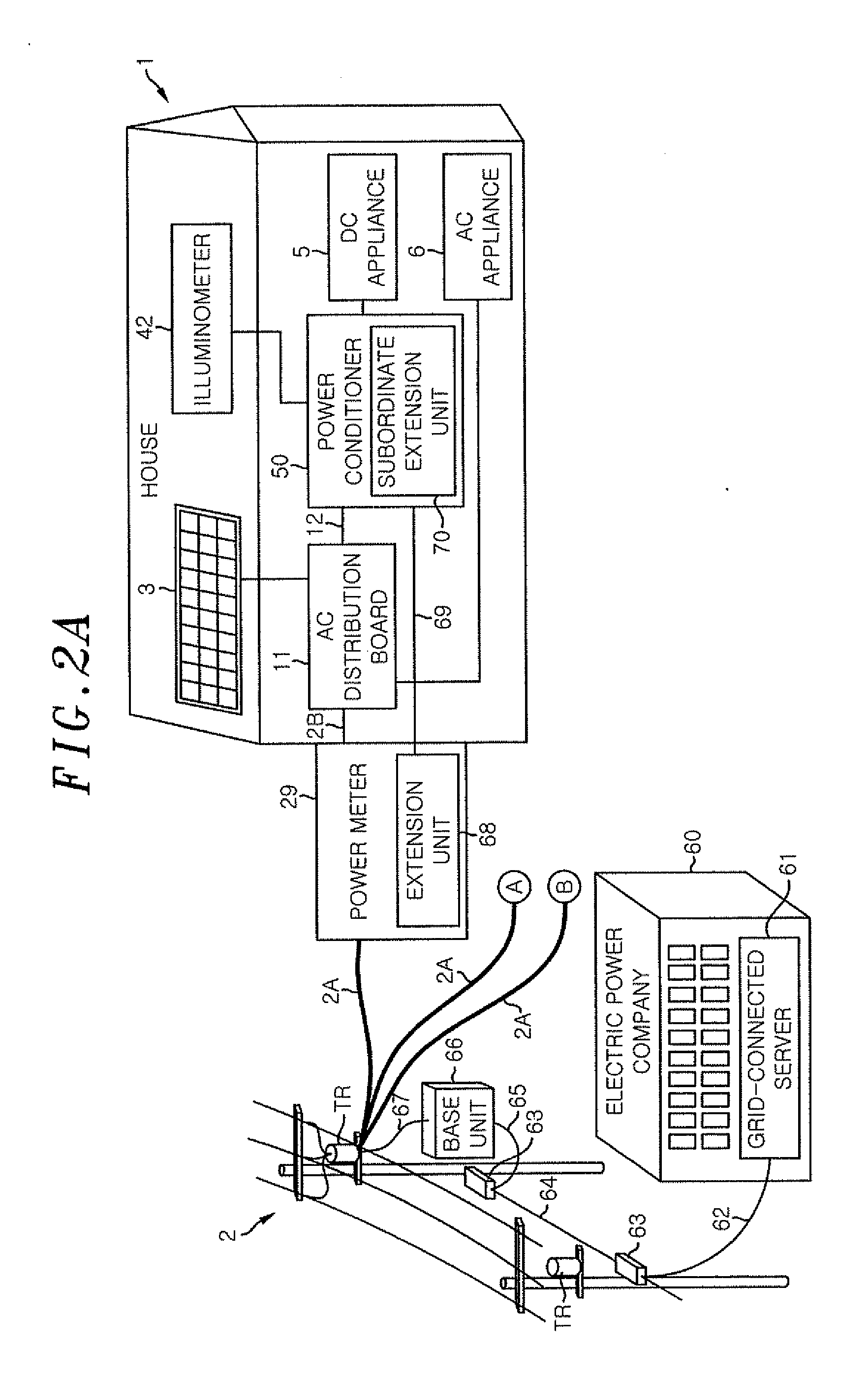
[0116]Next, the electric power management system in accordance with a second embodiment of the present invention will be described with reference to FIG. 7. FIG. 7 schematically illustrates a case where communications between a power meter 29 and a power conditioner 50 is performed through an external communications network N.

[0117]Further, the second embodiment differs from the first embodiment in that the communications between the power meter 29 and the power conditioner 50 is performed through the external communications network N. Other points remain the same as those of the first embodiment. In the present embodiment, description will be focused on the points differing from the first embodiment. Like reference numerals will be given to like parts, and redundant description thereof will be omitted for the sake of convenience.

[0118]As shown in FIG. 7, the extension unit 68 of the power meter 29 is communicatively connected to a base unit 66. The base unit 66 is communicatively c...

third embodiment

[0123]Next, an electric power management system in accordance with a third embodiment of the present invention will be described with reference to FIG. 8. FIG. 8 schematically illustrates a case where the communications between a power meter 29 and a power conditioner 50 is performed through a relay server 77 provided on the external communications network N.

[0124]Further, the third embodiment differs from the second embodiment in that the communications between the power meter 29 and the power conditioner 50 is performed through the relay server 77 provided on the external communications network N. Other points remain the same as those of the second embodiment. In the present embodiment, description will be focused on the points differing from the second embodiment. Like reference numerals will be given to like parts, and redundant description thereof will be omitted for the sake of convenience.

[0125]As shown in FIG. 8, the relay server 77 that enables the extension unit 68 of the ...


PUM


Abstract

An electric power management system includes a power generation apparatus for generating electric power, a power meter for receiving grid-connected information and a power conditioner for outputting the electric power generated by the power generation apparatus to the electric power system based on the grid-connected information. The grid-connected information is information related to stabilization of electric power of an electric power system from a management center for managing the electric power of the electric power system

Description

FIELD OF THE INVENTION[0001]The present invention relates to an electric power management system that performs an electric power management by associating an electric power generation apparatus, such as a photovoltaic power generation apparatus, with the electric power system of a commercial power source.BACKGROUND OF THE INVENTION[0002]Recently, the number of houses and offices equipped with a photovoltaic power generation apparatus (or solar cells) tends to increase. Power generation of the solar cell may be characterized that an increased amount of electric power is generated as the illuminance of sunlight grows higher, while a reduced amount of electric power is generated as the illuminance of sunlight becomes lower due to the rainy weather or other causes and no power is generated during the nighttime when there is no sunlight. For that reason, the power generation pattern thereof is not consistent with the power consumption pattern in houses or other places for many cases. Fur...

Claims


Application Information

Patent Timeline
Patent Type & Authority Applications(United States)
IPC IPC(8): H02J7/00H02J4/00
CPCH02J3/24H02J3/383H02J13/0006Y04S10/123Y02E10/563Y04S10/12H02J3/386Y02E10/763H02J7/35Y02E40/72Y02E10/566H02J3/387H02J2300/30H02J2300/28H02J2300/24H02J3/381H02J13/00034Y02E10/56Y02E10/76Y02E40/70H02J13/00002H02J3/46Y04S10/30Y04S10/52Y02E60/00
Inventor KUNIYOSI, KENJIMORI, SHINICHI
Owner PANASONIC INTELLECTUAL PROPERTY MANAGEMENT CO LTD
Why Eureka
Try Eureka