Wellbore plug isolation system and method

Active Publication Date: 2015-06-23
WELLS FARGO BANK NAT ASSOC +1
View PDF2 Cites 30 Cited by
  • Summary
  • Abstract
  • Description
  • Claims
  • Application Information

AI Technical Summary

Benefits of technology

[0032]Provide for eliminating undesired premature pres

Problems solved by technology

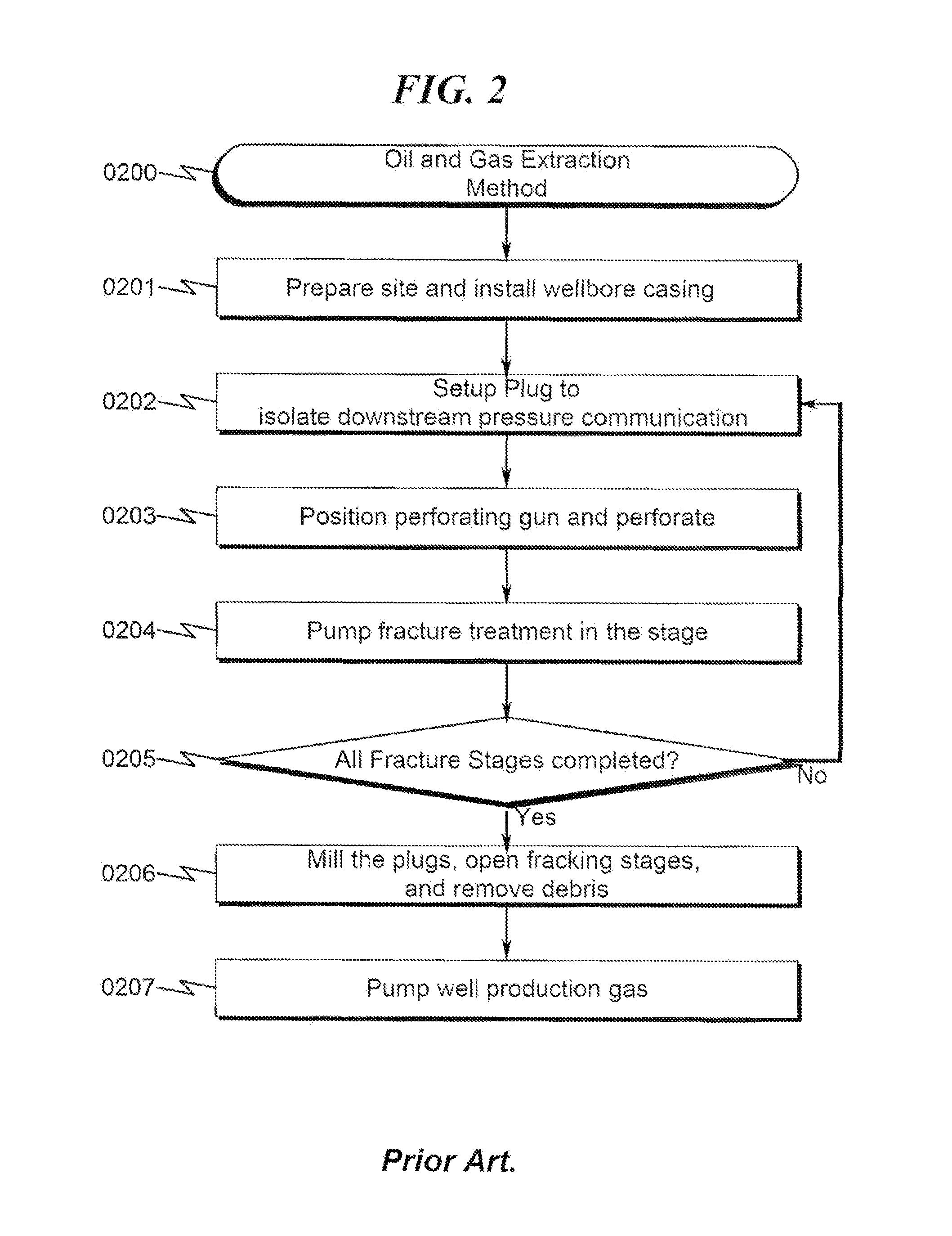
Additionally, frac plugs can be inadvertently set at undesired locations in the wellbore casing creating unwanted constrictions.
The constrictions may latch wellbore tools that are run for future operations and cause unwanted removal process.
Each trip is time consuming and expensive.
In addition, the process of drilling and milling the plugs creates debris that needs to be removed in another operation.
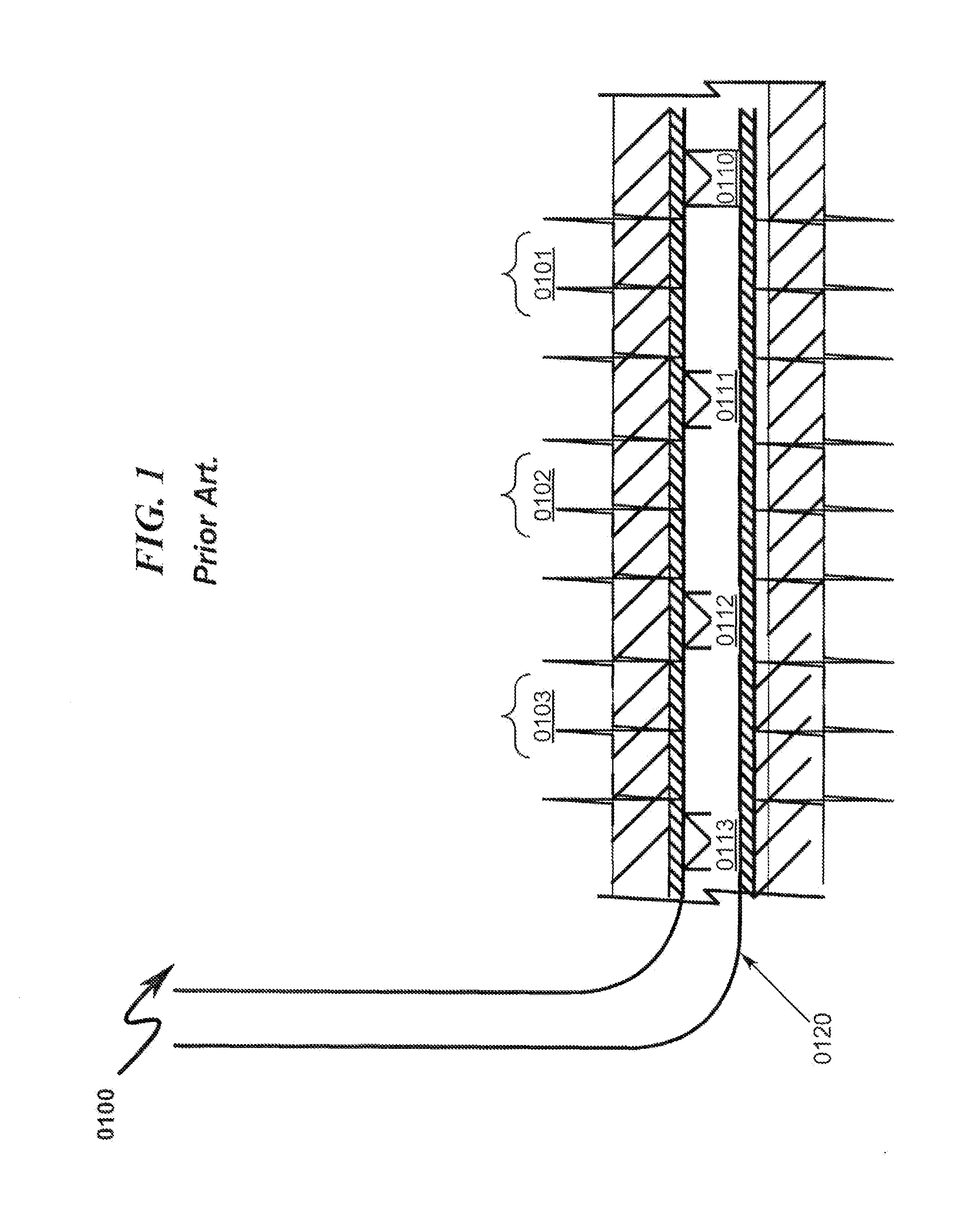
The prior art as detailed above suffers from the following deficiencies:Prior art systems do not provide for positioning a ball seat at a desired location after a wellbore casing has been installed, without depending on a predefined sleeve location integral to the wellbore casing to position the pl

Method used


Image

  • Wellbore plug isolation system and method
  • Wellbore plug isolation system and method
  • Wellbore plug isolation system and method

Examples


Embodiment Construction

[0093]While this invention is susceptible of embodiment in many different forms, there is shown in the drawings and will herein be described in detailed preferred embodiment of the invention with the understanding that the present disclosure is to be considered as an exemplification of the principles of the invention and is not intended to limit the broad aspect of the invention to the embodiment illustrated.

[0094]The numerous innovative teachings of the present application will be described with particular reference to the presently preferred embodiment, wherein these innovative teachings are advantageously applied to the particular problems of a wellbore plug isolation system and method. However, it should be understood that this embodiment is only one example of the many advantageous uses of the innovative teachings herein. In general, statements made in the specification of the present application do not necessarily limit any of the various claimed inventions. Moreover, some sta...


PUM


Abstract

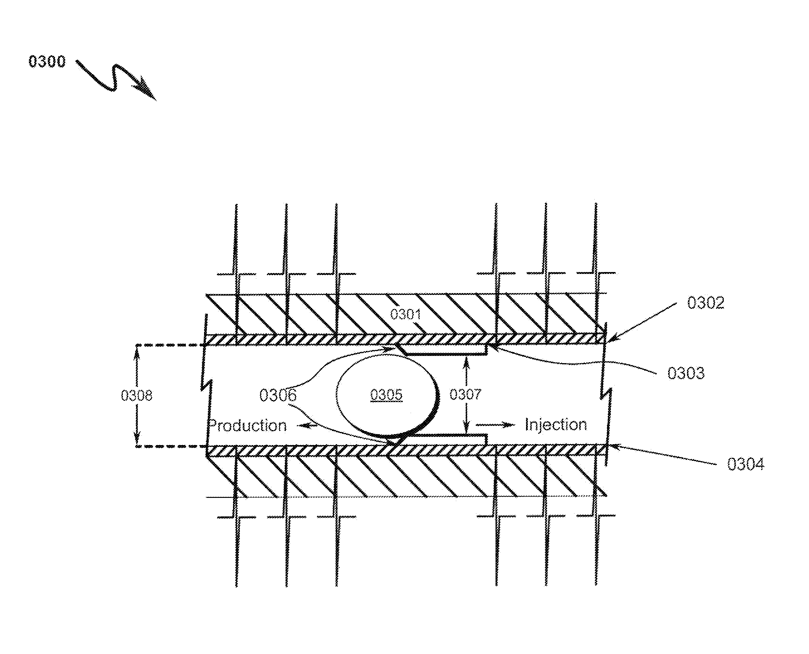
A wellbore plug isolation system and method for positioning plugs to isolate fracture zones in a horizontal, vertical, or deviated wellbore is disclosed. The system/method includes a wellbore casing laterally drilled into a hydrocarbon formation, a wellbore setting tool (WST) that sets a large inner diameter (ID) restriction sleeve member (RSM), and a restriction plug element (RPE). The WST is positioned along with the RSM at a desired wellbore location. After the WST sets and seals the RSM, a conforming seating surface (CSS) is formed in the RSM. The CSS is shaped to engage/receive RPE deployed into the wellbore casing. The engaged/seated RPE isolates heel ward and toe ward fluid communication of the RSM to create a fracture zone. The RPE's are removed or left behind prior to initiating well production without the need for a milling procedure. A large ID RSM diminishes flow constriction during oil production.

Description

CROSS REFERENCE TO RELATED APPLICATIONS[0001]Not ApplicablePARTIAL WAIVER OF COPYRIGHT[0002]All of the material in this patent application is subject to copyright protection under the copyright laws of the United States and of other countries. As of the first effective filing date of the present application, this material is protected as unpublished material.[0003]However, permission to copy this material is hereby granted to the extent that the copyright owner has no objection to the facsimile reproduction by anyone of the patent documentation or patent disclosure, as it appears in the United States Patent and Trademark Office patent file or records, but otherwise reserves all copyright rights whatsoever.STATEMENT REGARDING FEDERALLY SPONSORED RESEARCH OR DEVELOPMENT[0004]Not ApplicableREFERENCE TO A MICROFICHE APPENDIX[0005]Not ApplicableFIELD OF THE INVENTION[0006]The present invention generally relates to oil and gas extraction. Specifically, the invention attempts to isolate fr...

Claims


Application Information

Patent Timeline
IPC IPC(8): E21B43/26E21B43/25
CPCE21B43/25E21B43/14E21B43/26E21B43/103E21B23/01E21B33/128E21B33/12E21B43/116E21B23/06E21B31/002E21B33/1204E21B33/124
Inventor SNIDER, PHILIP MARTINGEORGE, KEVIN R.HARDESTY, JOHN T.WROBLICKY, MICHAEL D.CLARK, NATHAN G.ROLLINS, JAMES A.WESSON, DAVID S.
Owner WELLS FARGO BANK NAT ASSOC
Why Eureka
Try Eureka