Data processing apparatus and print data generating method
a data processing apparatus and data generating technology, applied in the field of data processing apparatus and print data generating method, can solve problems such as low image quality, and achieve the effect of reducing the texture of printed images
- Summary
- Abstract
- Description
- Claims
- Application Information
AI Technical Summary
Benefits of technology
Problems solved by technology
Method used
Image
Examples
first embodiment
(First Embodiment)
[0043]A binarization process using dot arrangement patterns according to the first embodiment of the present invention in the printing apparatus described above will now be described.
[0044]FIG. 3 is a diagram illustrating a nozzle array on a print head according to the present embodiment. FIG. 3 illustrates nozzle arrays that eject ink of one color. The nozzle arrays for one ink color are made up of a nozzle array “a” and a nozzle array “b”. Ejection ports (nozzles) in the nozzle array a and the nozzle array b are respectively arrayed at a density of 600 dpi, and in addition, the nozzle array a and the nozzle array b are disposed shifted from each other by 1200 dpi in the sub-scan direction. Thus, the print head of the present embodiment is able to print at 1200 dpi resolution in the sub-scan direction.
[0045]FIGS. 4A and 4B are diagrams illustrating dot arrangement patterns of the present embodiment, and illustrate dot arrangement patterns in the case of printing a...
second embodiment
(Second Embodiment)
[0061]The foregoing first embodiment relates to a configuration that generates shift values by using random numbers, but the present invention is not limited to this configuration. FIG. 12 is a diagram similar to FIG. 6 according to the first embodiment, and illustrates shift values generated by a shift value generating section 507 according to the second embodiment of the present invention. As illustrated in FIG. 12, the present embodiment generates regular shift values in the main scan direction and the sub-scan direction.
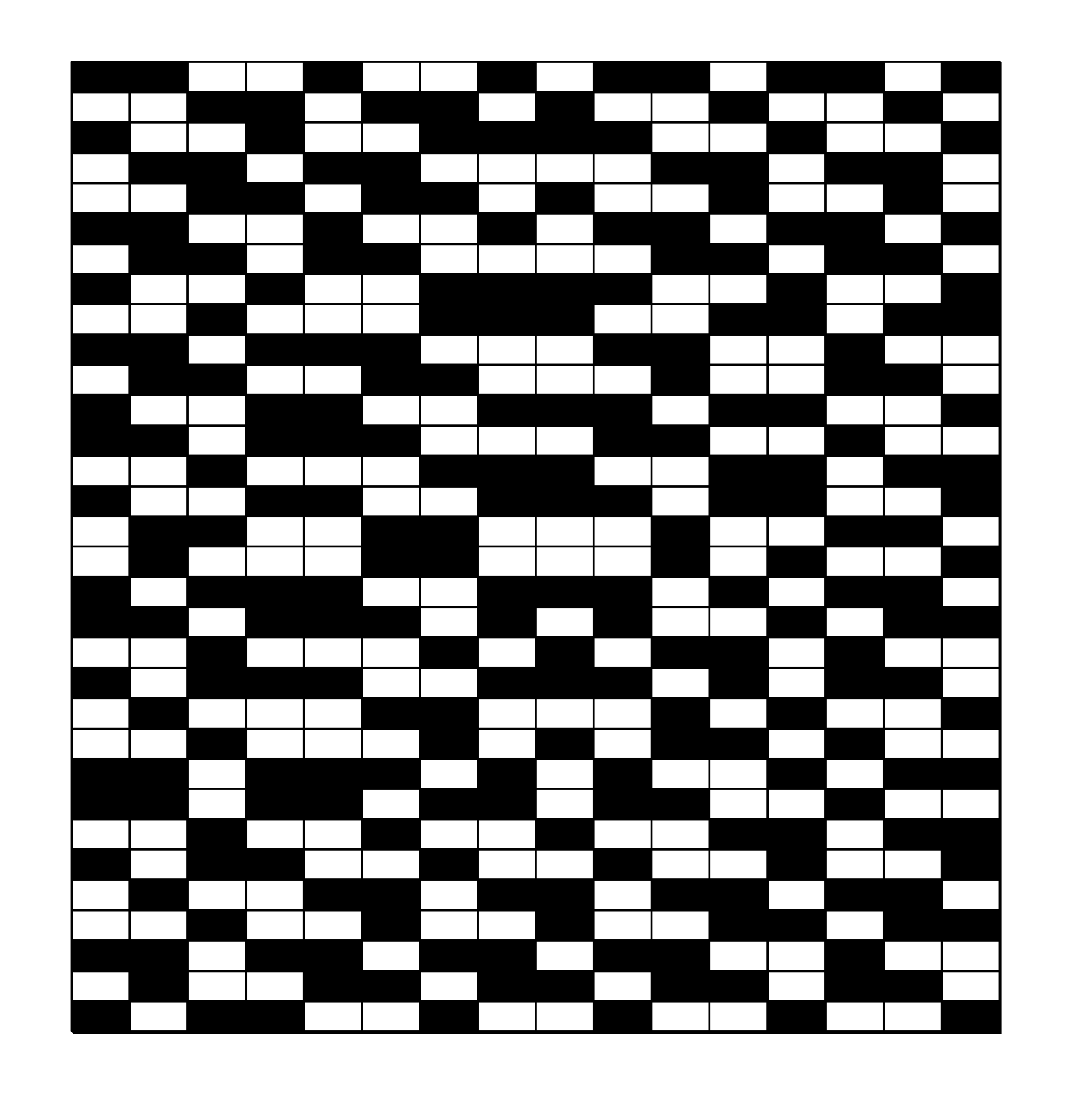
[0062]FIG. 13 is a diagram illustrating the results of developing dot arrangement patterns according to the shift process illustrated in FIGS. 7A and 7B, using the regular shift values illustrated in FIG. 12. As illustrated in FIG. 13, it is still possible to reduce regular textures even in the case of using regular shift values as in the present embodiment.
third embodiment
(Third Embodiment)
[0063]The first embodiment and the second embodiment relate to a process that one-dimensionally allocates a value (address) calculated on the basis of a shift value to each cell position (X, Y) in a base matrix, and shifts each dot arrangement pattern such that cell where the address is 1% 16 moves to the pixel position (0, 0). The shift process is obviously not limited to this configuration.
[0064]FIG. 14 is a diagram illustrating shift values (X, Y) generated by a shift value generating section 507 according to the third embodiment of the present invention. As illustrated in FIG. 14, in the present embodiment, shift values are generated on the basis of two-dimensional cell positions (X, Y) in a base matrix. In other words, the shift value generating section 507 generates coordinates with random numbers in the ranges of 0≦X
PUM
 Abstract
Description
Claims
Application Information
 - R&D
- Intellectual Property
- Life Sciences
- Materials
- Tech Scout
- Unparalleled Data Quality
- Higher Quality Content
- 60% Fewer Hallucinations
Browse by: Latest US Patents, China's latest patents, Technical Efficacy Thesaurus, Application Domain, Technology Topic, Popular Technical Reports.
© 2025 PatSnap. All rights reserved.Legal|Privacy policy|Modern Slavery Act Transparency Statement|Sitemap|About US| Contact US: help@patsnap.com


