

Cloth cutting device, cloth cutting method, and cloth cutting and stacking method
a cutting device and cloth technology, applied in metal working devices, severing textiles, textiles and paper, etc., can solve the problems of difficult cutting, difficult to handle textiles with this degree, and difficult to achieve desired shape, etc., to achieve the effect of easy and precise cutting of textiles
- Summary
- Abstract
- Description
- Claims
- Application Information
AI Technical Summary
Benefits of technology
Problems solved by technology
Method used
Image

Examples
Embodiment Construction
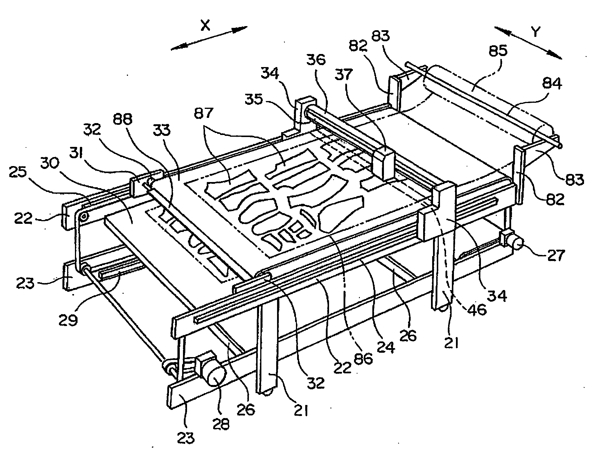
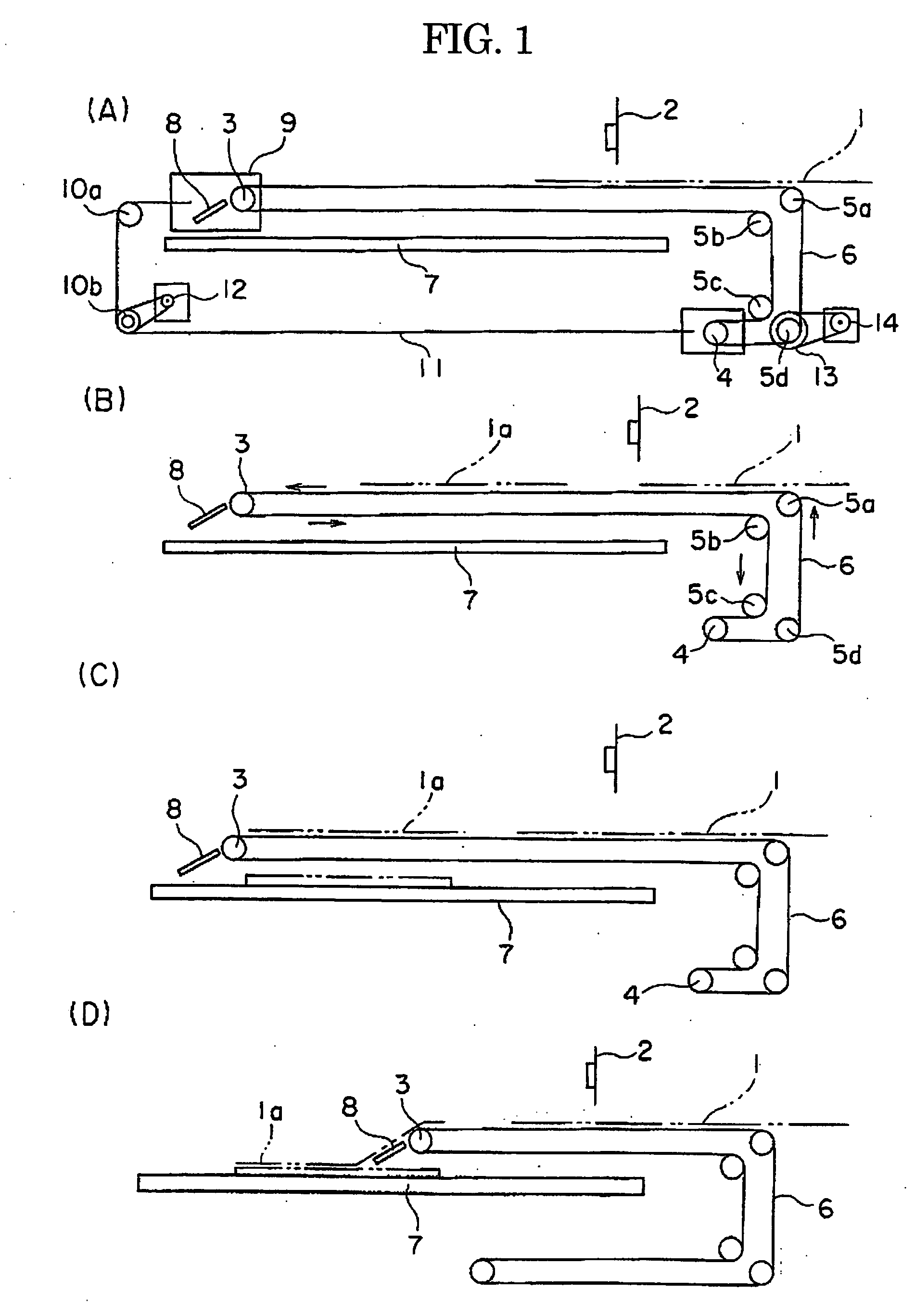
[0032] As described earlier, the texture is separated from the conveyor belt or the fixed sheet at least during the cutting in the present invention so that the texture cutting is not directly influenced by the conveyor belt or the fixed sheet. The means therefor is not especially restricted, and ordinarily the synchronizing member which runs in synchronization with the cutter is placed between the conveyor belt or the fixed sheet below the cutter and the texture, and the cutter is descended to cut the texture on the synchronizing member.
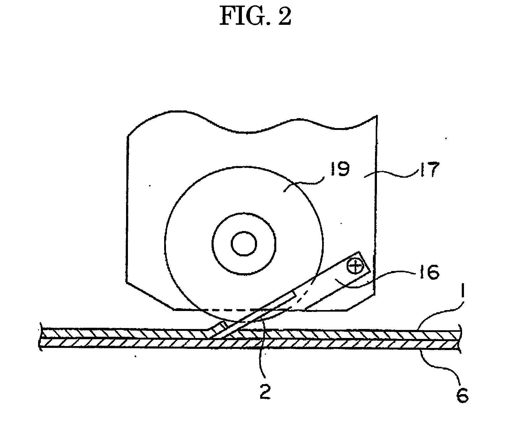
[0033] The cutter is ordinarily accommodated in a cutter head which runs in the width direction (Y-direction) of the conveyor belt conveying the texture or the fixed sheet. A carriage which runs the cutter head runs in the length direction (X-direction) of the conveyor belt or the fixed sheet. The combination of the running of the cutter head and the carriage makes the cutter reach any position on the texture. The cutter is rotatably supported arou...
PUM
| Property | Measurement | Unit |
|---|---|---|
| width | aaaaa | aaaaa |
| width | aaaaa | aaaaa |
| period of time | aaaaa | aaaaa |
Abstract
Description
Claims
Application Information