Abrasive tape for texturing magnetic recording media

Inactive Publication Date: 2001-02-27
DIAMONDOP
View PDF18 Cites 14 Cited by
  • Summary
  • Abstract
  • Description
  • Claims
  • Application Information

AI Technical Summary

Problems solved by technology

Optimization of the read/write head interface surface of magnetic recording media for both mechanical durability and high-density recording characteristics has been problematic, requiring compromises between competing criteria.
Additionally, imposing the data zone texturing over the contact start stop zone texture ensures that stiction performance is not compromised, but cannot guarantee the error performance of the data zone.
Conversely, imposing the contact start stop zone texturing over the data zone texture guarantees the error performance throug

Method used


Image

  • Abrasive tape for texturing magnetic recording media
  • Abrasive tape for texturing magnetic recording media
  • Abrasive tape for texturing magnetic recording media

Examples


Example

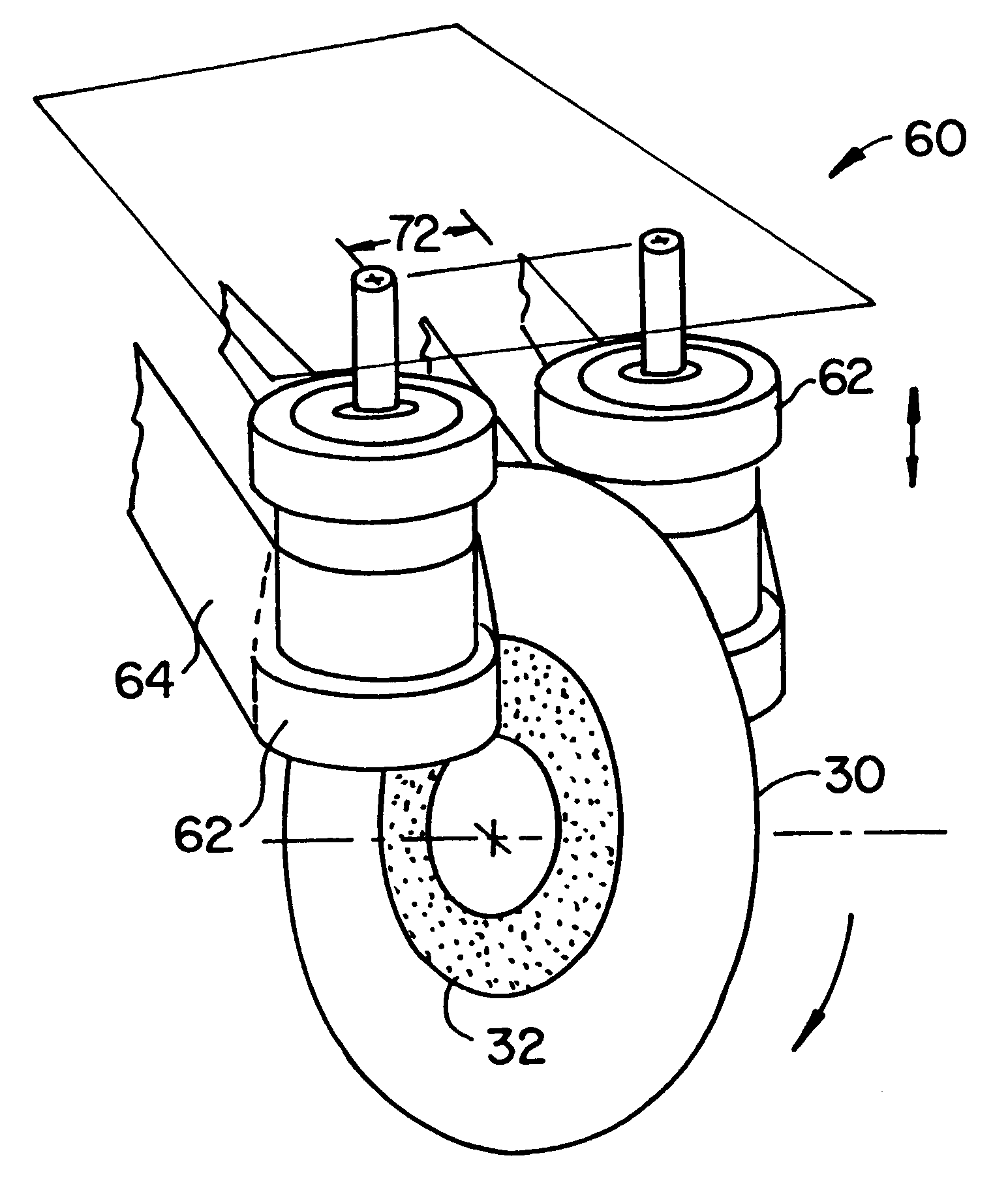
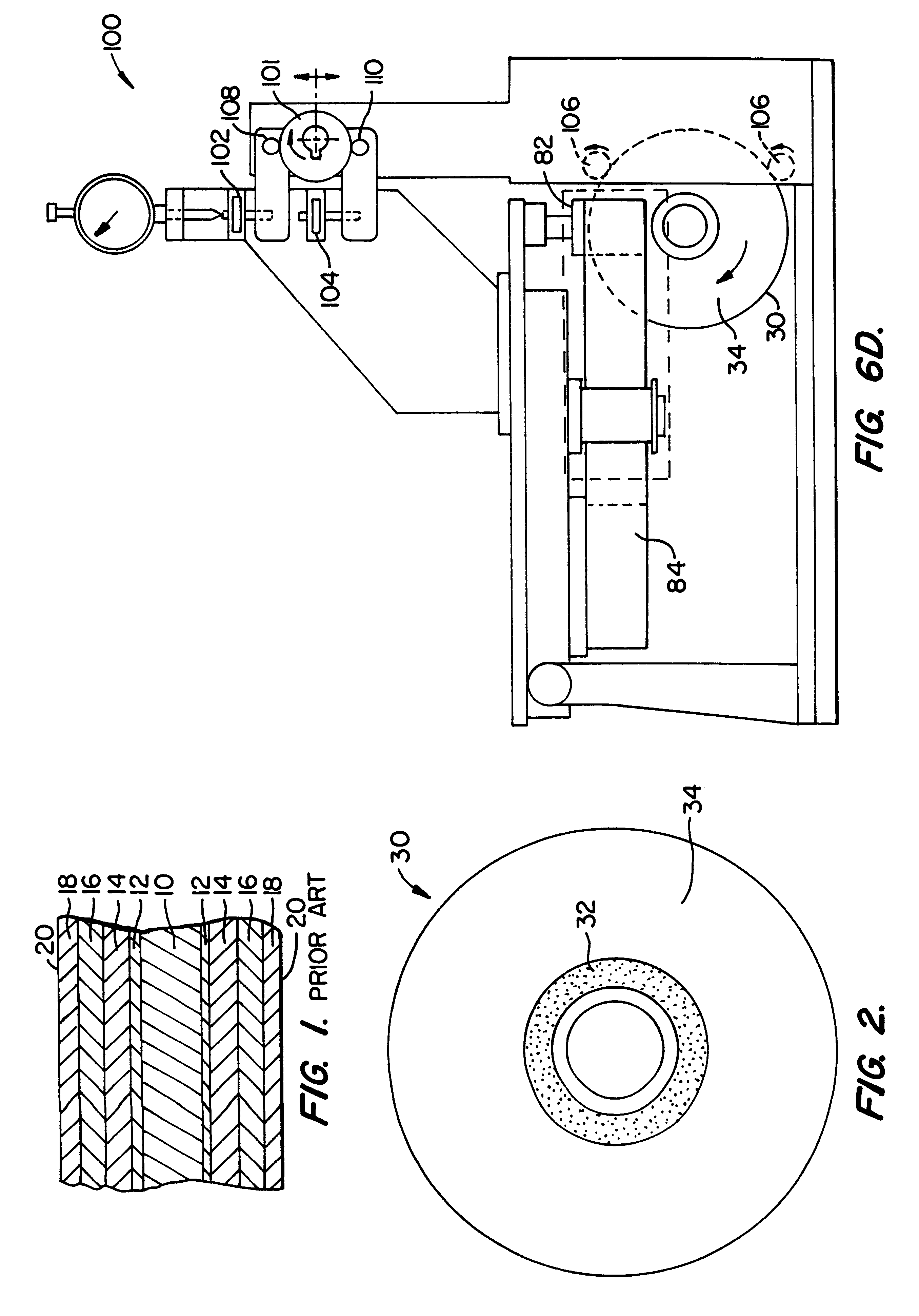
Referring now to FIG. 2, magnetic recording media according to the present invention will usually be in the form of a magnetic recording disk 30 having a contact start stop zone 32 and a data zone 34. These zones are distinguished by the surface texture, the properties of which will be described with reference to the outermost surface of the disk as it is used in a magnetic recording system. The actual texturing processes may be performed on the substrate, on an underlayer below the magnetic recording layers, on the magnetic recording layer itself, or on an overlayer.

Typically, an underlayer is textured, most commonly an Ni--P layer. The average surface roughness, and other surface topology described herein, refers specifically to the surface characteristics of the outermost layer, rather than the characteristics of the textured surface prior to application of any overlayers. Although the data zone is shown in an outward location, the relative radial position of the zones may be rev...


PUM


Abstract

Magnetic recording media are provided having separately textured data and read/write head landing zones. Separating these zones on the recording surface allows independent optimization of the topology to maximize both recording characteristics and mechanical durability. The landing or contact start stop zone has an average surface roughness greater than that of the data zone. Preferably, a transition zone extends between the contact start stop zone and the data zone, the transition zone varying between the two in average surface roughness. Preferably, the contact start stop zone is textured first, followed by the data zone, thereby ensuring uniform stiction performance. Texture machines for producing such zone texturing and texturing methods are also provided.

Description

1. Field of the InventionThe present invention relates to generally to magnetic recording media, and more particularly to recording media having a landing zone with an independently optimized surface texture.Magnetic recording disks generally comprise a disk substrate having a magnetic layer and a number of underlayers and overlayers deposited thereon. The nature and composition of each layer is selected to provide desired magnetic recording characteristics. An exemplary present day disk is illustrated in FIG. 1 and comprises a non-magnetic disk substrate 10 typically composed of an aluminum alloy. Alternative substrates comprise non-metallic materials such as glass, ceramics, glass ceramic composites, carbon, carbon ceramic composites, and the like. Generally, an amorphous nickel phosphorus (Ni--P) layer 12 is formed over each surface of disk substrate 10, typically by plating. The Ni--P layer is hard, and imparts rigidity to aluminum alloy substrates. A chromium ground layer 14 is...

Claims


Application Information

Patent Timeline
IPC IPC(8): B24B21/06B24B21/04G11B5/84G11B5/64G11B5/82
CPCB24B21/06G11B5/64G11B5/8404G11B5/82Y10S428/90Y10T428/24355
Inventor WEISS, JOEL R.SHIMA, KOJILEIGH, JOSEPHKONISHI, HIROSHIKURATAKA, NOBUOHARA, HIROKIINOUE, NAOKI
Owner DIAMONDOP
Why Eureka
Try Eureka