Seat bench transport device

Inactive Publication Date: 2015-06-30
AIRBUS OPERATIONS GMBH
View PDF20 Cites 3 Cited by
  • Summary
  • Abstract
  • Description
  • Claims
  • Application Information

AI Technical Summary

Benefits of technology

The invention is a seat bench transport device that solves the problems of the prior art by allowing for the safe transport of seat benches with different foot spacing between the seats.

Problems solved by technology

The laborious, time-consuming activity of sliding the seat benches in the lengthwise or crosswise direction of the seat bench transport device is no longer necessary.
This also saves installation time.

Method used


Image

  • Seat bench transport device
  • Seat bench transport device
  • Seat bench transport device

Examples


Embodiment Construction

[0038]The same structural elements bear the same reference numbers, although for the sake of clarity not all of the elements are identified with their reference number in some of the figures.

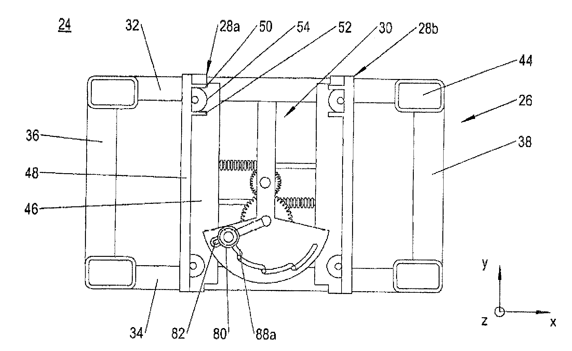
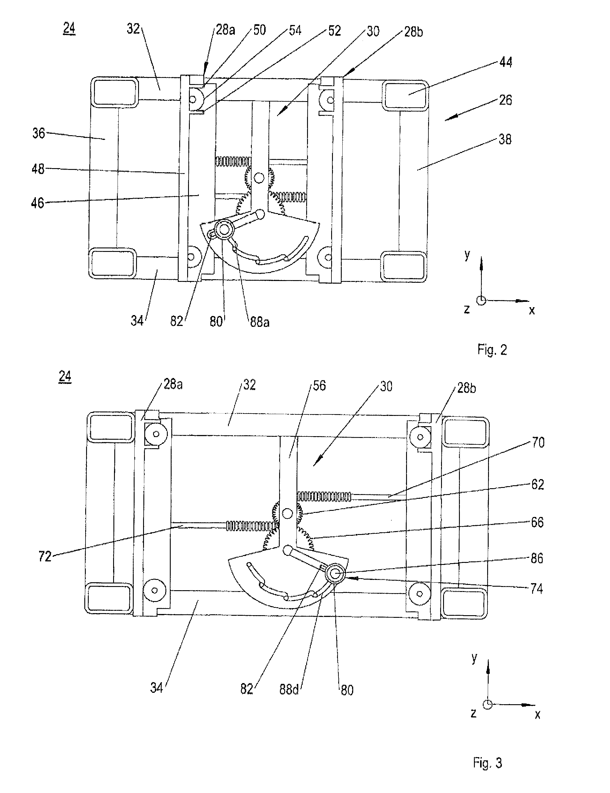
[0039]In the plan views of FIGS. 2 and 3, in the side view of FIG. 4, and in the detail view of FIG. 5, a first embodiment of a seat bench transport device 24 is shown. This comprises a chassis 26, two retaining rails 28a, 28b and a displacement device 30 for moving retaining rails 28a, 28b in opposite directions.

[0040]Chassis 26 comprises a base frame, which is formed by two side members 32, 34 and two cross members 36, 38 which connect side members 32, 34 to one another at the extremities thereof. Side members 32, 34 define a longitudinal direction x of seat bench transport device 1 and cross members 36, 38 define a transverse direction y of seat bench transport device 1.

[0041]In order to move chassis 26, as shown in FIG. 4 seat bench transport device 1 is equipped with two caster pairs 40, 42...


PUM


Abstract

A seat bench transport device for transporting a bench of seats for a vehicle, comprising a chassis, a retaining rail pair that is arranged on the chassis and including two retaining rails extending parallel to one another for accommodating seat bench feet. The lengthwise sides of these rails that face one another are open at least in sections and the lengthwise sides thereof that face away from one another each have at least one locking section. A displacement mechanism moves the retaining rails transversely relative to one another.

Description

CROSS-REFERENCES TO RELATED APPLICATIONS[0001]This application claims the benefit of the U.S. Provisional Application No. 61 / 533,809, filed on Sep. 13, 2011, and of the German patent application No. 10 2011 082 602.5 filed on Sep. 13, 2011, the entire disclosures of which are incorporated herein by way of reference.BACKGROUND OF THE INVENTION[0002]The invention relates to a seat bench transport device for transporting a seat bench for a transport vehicle.[0003]Seat benches for use as seating in aircraft are usually transported to the aircraft on a mobile outside device, then loaded onto a mobile inside device and moved with this inside the aircraft fuselage to their respective installation positions. A conventional outside device for transporting a seat bench to the aircraft is shown in FIG. 1. This outside device 1 for transporting a seat bench 2 comprises a pallet 8 that is movable on caster pairs 4, 6, and on which a plurality of seat rail pairs is mounted securely in the transve...

Claims


Application Information

Patent Timeline
IPC IPC(8): B62B1/00B62B3/02B62B3/16B62B3/04B62B3/10
CPCB62B3/02B62B3/16B62B3/04B62B3/10B62B2202/32B62B2203/44B62B2206/02B64F5/50
Inventor GROSSE-PLANKERMANN, PETERBARDENHAGEN, THOMASPIETZ, UWE
Owner AIRBUS OPERATIONS GMBH
Why Eureka
Try Eureka