Method for automatically adjusting the defrost interval in a heat pump system

a heat pump and automatic adjustment technology, applied in the direction of defrosting, instruments, domestic cooling apparatus, etc., can solve the problems of reducing the performance of degrading the heat exchanger and system performance, heating capacity and efficiency, etc., to reduce the frequency of defrost cycles, eliminate the formation of excessive amounts of frost, and simple and robust

Active Publication Date: 2015-06-30
CARRIER CORP
View PDF2 Cites 4 Cited by
  • Summary
  • Abstract
  • Description
  • Claims
  • Application Information

AI Technical Summary

Benefits of technology

[0015]The present disclosure provides a method of defrost control that is simple and robust, and that dynamically adjusts to changing conditions to ensure problem-free operation of a heat pump system. The primary focus is to eliminate the formation of excessive amounts of frost, while still reducing the frequency of defrost cycles when operating under less severe conditions.

Problems solved by technology

Heat pump systems generally build frost on the outdoor heat exchanger coil when operating in the heating mode.
This frost build-up can gradually degrade the heat exchanger and system performance in the form of heating capacity and efficiency.
At this point, in most heat pump systems, protective devices typically cause the system to shut down.
If the protective devices are not effective, equipment failure could occur.
Running the heat pump in cooling mode while the home needs heating capacity clearly leads to wasted energy.
Furthermore, the cold air delivered inside the home can be quite uncomfortable in the heating season.
Typically, this supplemental source is electric strip heat, which itself consumes a great amount of electric energy.
Another problem is that two refrigerant flow reversals are needed in a defrost cycle, from heating to cooling and back to heating.
The flow reversals are usually quite noisy, and are an annoyance to the consumer.
This can be quite challenging because the rate of frost build up varies with the weather.
Determining when to initiate a defrost cycle is more challenging.
Since there is no practical direct sensing of frost level, these demand defrost methods use surrogate sensors to provide an estimate of the frost level.
These methods are not completely foolproof.
They may defrost too frequently or too infrequently.
The consequences are either a “block of ice” on the coils or complaints by consumers about too many defrosts.
A fixed “timed” defrost interval cannot always match the current defrost needs.
This can lead to the same problems as “demand” defrosts.

Method used


Image

  • Method for automatically adjusting the defrost interval in a heat pump system
  • Method for automatically adjusting the defrost interval in a heat pump system

Examples


Embodiment Construction

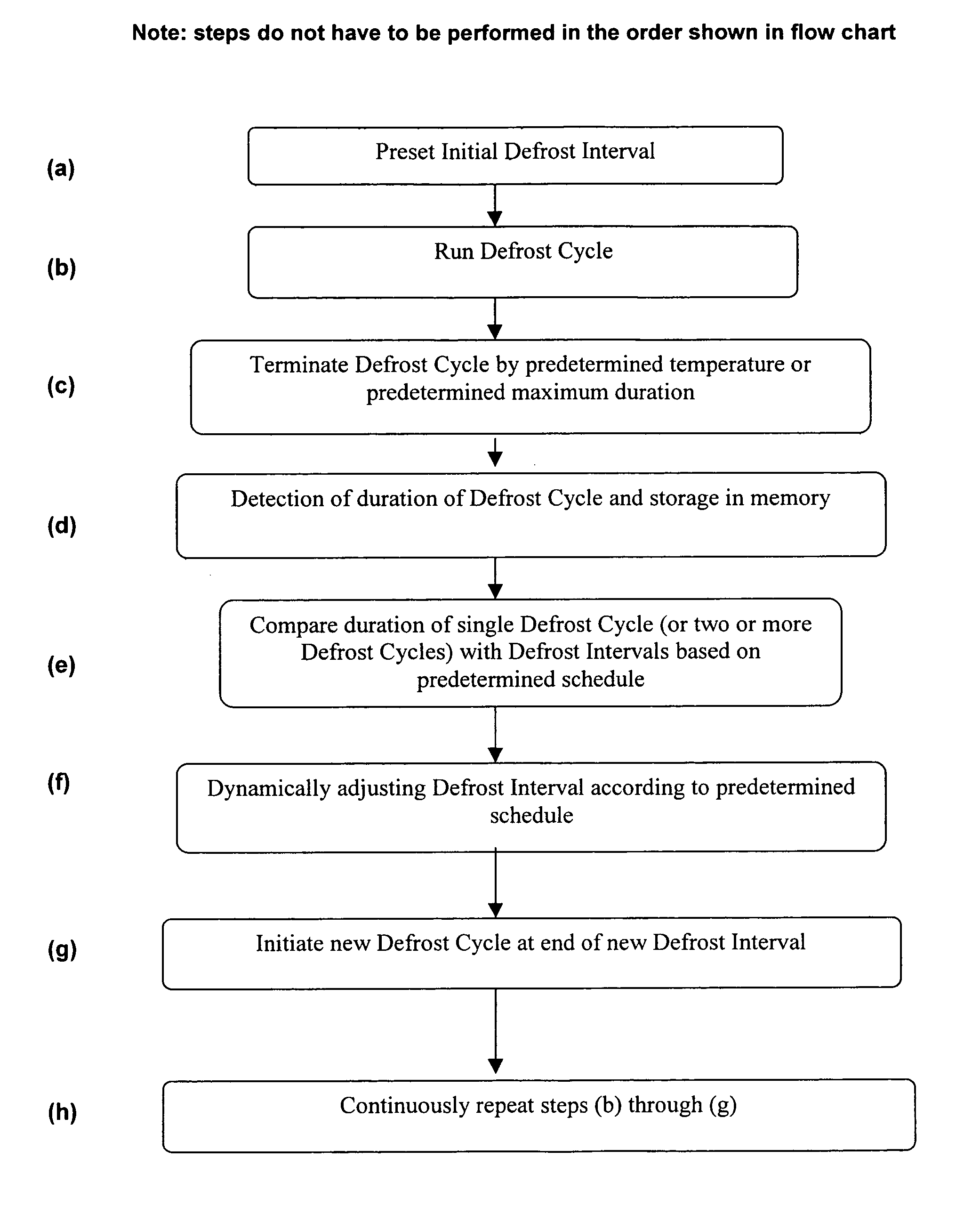
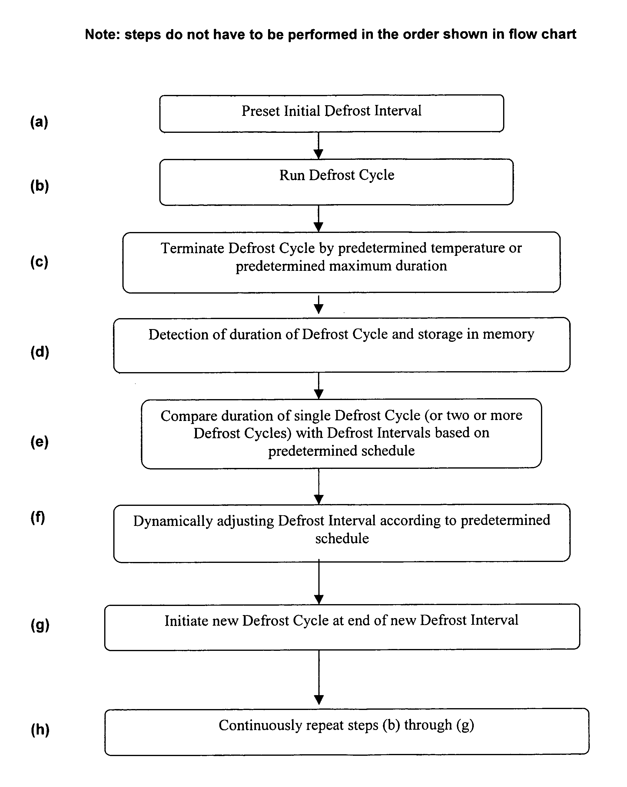
[0018]The present disclosure provides a method to dynamically and automatically adjust the interval of time between defrost cycles in a heat pump system. The method involves tracking the time duration of the previous defrost cycle (or cycles) and then dynamically adjusting the length of time before the next defrost cycle is initiated.

[0019]During a defrost cycle, also called a defrost routine, the heat that flows into the heat exchanger coil is first consumed in melting the frost, if any, that has previously built up on the coil. Once the frost is cleared, the heat quickly increases the temperature of the coil. The defrost control, upon sensing this increased coil temperature, terminates the defrost cycle. The time duration of a defrost cycle, therefore, primarily depends on the amount of previously accumulated frost on the coil. Greater amounts of accumulated frost result in longer defrost cycles. For example, in typical residential heat pump systems, defrost cycles range between o...


PUM


Abstract

The present invention relates generally to a method for automatically adjusting the interval of time between defrost cycles in a heat pump system. The method includes tracking the duration of the previous defrost cycle or cycles, and dynamically adjusting the length of time before initiating the next defrost cycle.

Description

CROSS-REFERENCE TO A RELATED APPLICATION[0001]The present application claims priority in U.S. Provisional Patent Application No. 60 / 760,540, filed Jan. 20, 2006, which is incorporated in its entirety by reference herein.BACKGROUND OF THE INVENTION[0002]1. Field of the Invention[0003]The present invention relates generally to a method for automatically adjusting the interval of time between defrost cycles in a heat pump system. The method utilizes measurements of the duration of the previous defrost cycle or cycles, and adjusts the time interval before initiating the next defrost cycle so that any frost build-up can be defrosted without unnecessary defrost cycles.[0004]2. Description of the Related Art[0005]Heat pump systems generally build frost on the outdoor heat exchanger coil when operating in the heating mode. This frost build-up can gradually degrade the heat exchanger and system performance in the form of heating capacity and efficiency. If the frost is not cleared, it can co...

Claims


Application Information

Patent Timeline
Patent Type & Authority Patents(United States)
IPC IPC(8): F25D21/02F25D21/00G05D23/32F25D21/06
CPCF25D21/008
Inventor SHAH, RAJENDRA K.
Owner CARRIER CORP
Why Eureka
Try Eureka