Lens unit and method for manufacturing the same

a technology of lens unit and lens body, which is applied in the field of lens unit, can solve the problems of insufficient use of the disclosed lens unit in the mobile electronic device camera module, difficult optical axis adjustment etc., and achieve the effect of reducing the thickness not complicating the structure of the lens unit, and preventing the reduction of thickness

Active Publication Date: 2015-06-30
NANCHANG O FILM OPTICAL ELECTRONICS TECH CO LTD
View PDF6 Cites 15 Cited by
  • Summary
  • Abstract
  • Description
  • Claims
  • Application Information

AI Technical Summary

Benefits of technology

[0010]An object of the present invention is to provide a lens unit for allowing easy optical axis adjustment and reduction in thickness and a method for manufacturing the same.
[0015]In the present invention, the flange portion of the first lens is flush with the front surface of the protruding part provided in the frame main body. The thin light shielding film is affixed to at least one of the flange portion of the first lens and the front surface of the protruding part. When compared with the conventional case in which a plate-like lid is attached, the thickness of the lens unit is reduced by eliminating the thickness of the plate-like lid. The protruding part is provided at the front end of the frame main body, to position the second lens in the optical axis direction. The frame opening is formed in the protruding part. With the use of the space surrounded by the frame opening, the first lens is shifted in the direction orthogonal to the optical axis and thus the optical axis adjustment is performed. The optical axis adjustment function does not make the structure of the lens unit complicated and does not hinder the reduction in thickness.

Problems solved by technology

In this configuration, each lens is incorporated into the lens holding frame, so that the optical axis adjustment of the lens unit is difficult.
The disclosed lens unit is inadequate for use in the camera module in the mobile electronic device.

Method used


Image

  • Lens unit and method for manufacturing the same
  • Lens unit and method for manufacturing the same
  • Lens unit and method for manufacturing the same

Examples


Embodiment Construction

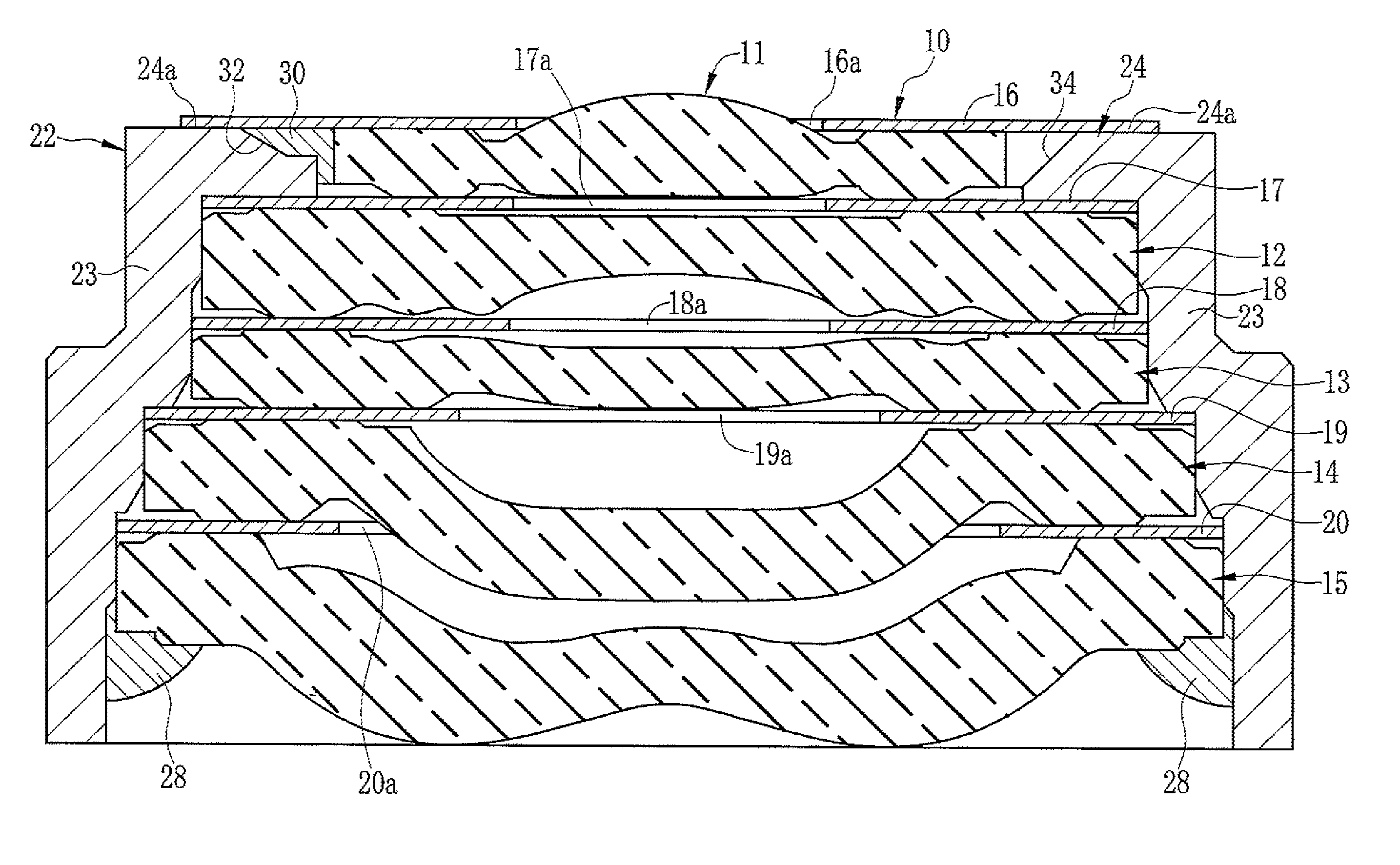
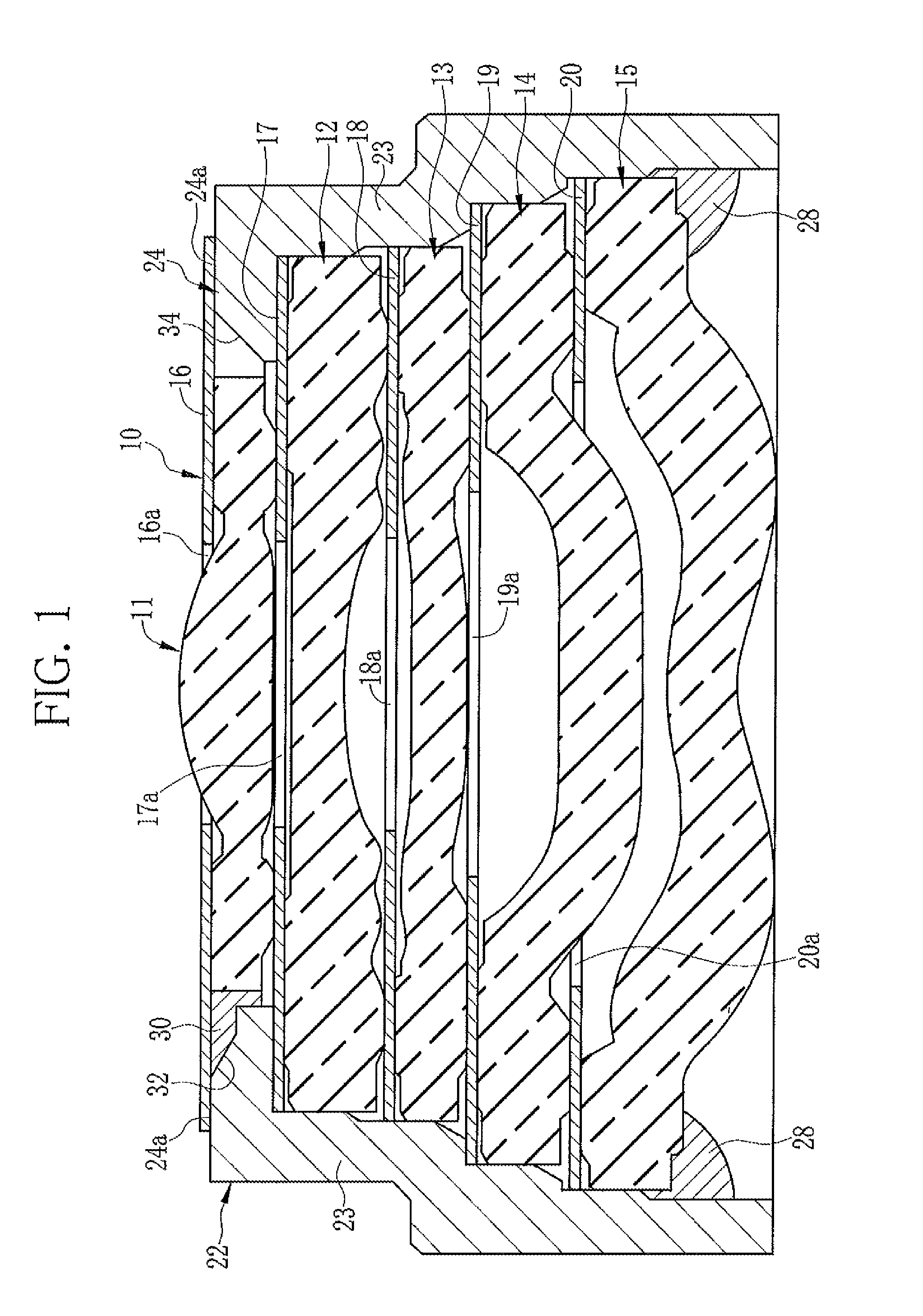
[0030]As shown in FIG. 1, a lens unit 10 is composed of five lenses (first to fifth lenses) 11 to 15, five light shielding films (first to fifth light shielding films) 16 to 20, and a holding frame 22 for holding them. The lens unit 10 is used in a camera module of a mobile electronic device such as a mobile phone or a mobile personal computer. Optical properties of each of the lenses 11 to 15 are adjusted such that a subject image is formed on an image sensor of the camera module when the lens unit 10 is mounted on the camera module.

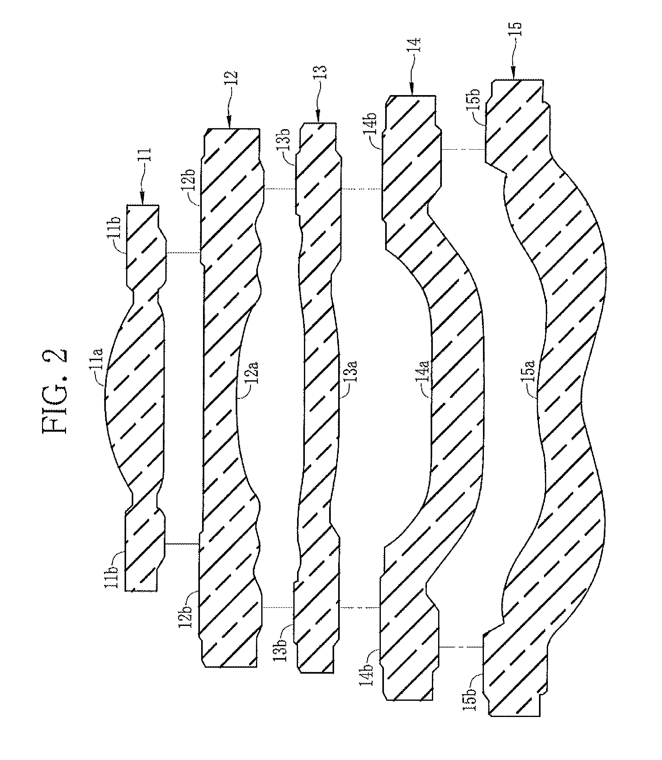
[0031]Each of the lenses 11 to 15 is formed into a disc-like (circular plate-like) shape. Each of the lenses 11 to 15 is formed such that the diameters of the lenses 11 to 15 decrease toward the lens on the light incident side (front side). In other words, the rearmost fifth lens 15 has the largest diameter and the first lens 11 has the smallest diameter, among the lenses 11 to 15. Note that the term “circle” as in the “circular plate-like shape” of eac...


PUM

PropertyMeasurementUnit
thicknessaaaaaaaaaa
thicknessaaaaaaaaaa
diameteraaaaaaaaaa

Abstract

A holding frame of a lens unit has a frame main body of a cylindrical shape, which corresponds to the shapes of lenses. A protruding part is provided at a front end of the frame main body. The protruding part protrudes to the inside of the frame main body. The thickness of the protruding part is the same as that of a flange portion of a first lens. When the first lens is fitted into a space formed by the protruding part, a front surface of the flange portion of the first lens is flush with a front surface of the protruding part. A first light shielding film, which functions as an aperture stop, is affixed to at least one of the flange portion of the first lens and the front surface of the protruding part.

Description

CROSS REFERENCE TO RELATED APPLICATIONS[0001]This application is a continuation of PCT / JP2012 / 073269 filed on Sep. 12, 2012, which claims foreign priority to Japanese Application No. 2011-216986 filed on Sep. 30, 2011. The entire contents of each of the above applications are hereby incorporated by reference.BACKGROUND OF THE INVENTION[0002]1. Field of the Invention[0003]The present invention relates to a lens unit in a camera module of a mobile electronic device and a method for manufacturing a lens unit.[0004]2. Description Related to the Prior Art[0005]There are mobile electronic devices such as mobile phones and mobile personal computers which comprise camera functions. A camera module used in the mobile electronic device is composed of an image sensor for capturing a subject image, a lens unit for forming the subject image on the image sensor, a signal processing circuit for processing an image signal from the image sensor, a flexible wiring substrate for electrically connectin...

Claims


Application Information

Patent Timeline
Patent Type & Authority Patents(United States)
IPC IPC(8): G02B7/02G02B13/00
CPCG02B7/021G02B7/02Y10T29/49826G02B13/0045
Inventor TAKASE, YOSHIYUKISHIMIZU, MOTOKAZU
Owner NANCHANG O FILM OPTICAL ELECTRONICS TECH CO LTD
Why Eureka
Try Eureka