Optical component

a technology of optical components and components, applied in the field of optical components, can solve problems such as processing quality problems, and achieve the effect of small size and easy adjustment of the optical axis during us

Inactive Publication Date: 2011-11-03
PUBLIC UNIVERSITY CORPORATION OSAKA CITY UNIVERSITY +2
View PDF4 Cites 7 Cited by
  • Summary
  • Abstract
  • Description
  • Claims
  • Application Information

AI Technical Summary

Benefits of technology

[0019]The optical component of the present invention can provide a carbon dioxide laser processing apparatus having a smaller size and can provide an easy adjustment of the optical axis during use.

Problems solved by technology

However, when irradiating an object to be processed with this linearly polarized carbon dioxide laser light, a problem in processing quality may occur because a processed width may vary depending on polarization direction of the carbon dioxide laser light.

Method used


Image

  • Optical component
  • Optical component
  • Optical component

Examples


embodiment 1

Optical Component

[0035]The section below will describe an embodiment of an optical component of the present invention in detail with reference to the attached drawings. In the description below, the optical component of the present invention will be described by an example of an optical element for converting a polarization state of carbon dioxide laser (transmission-type polarization filter). In the following drawings, a concave-and-convex structure formed on the surface of the optical component is illustrated in an exaggerated manner for clear understanding.

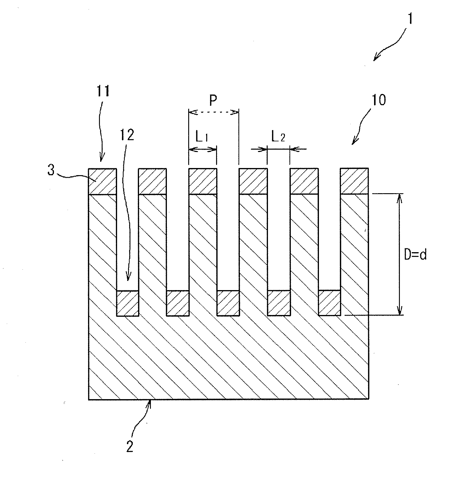
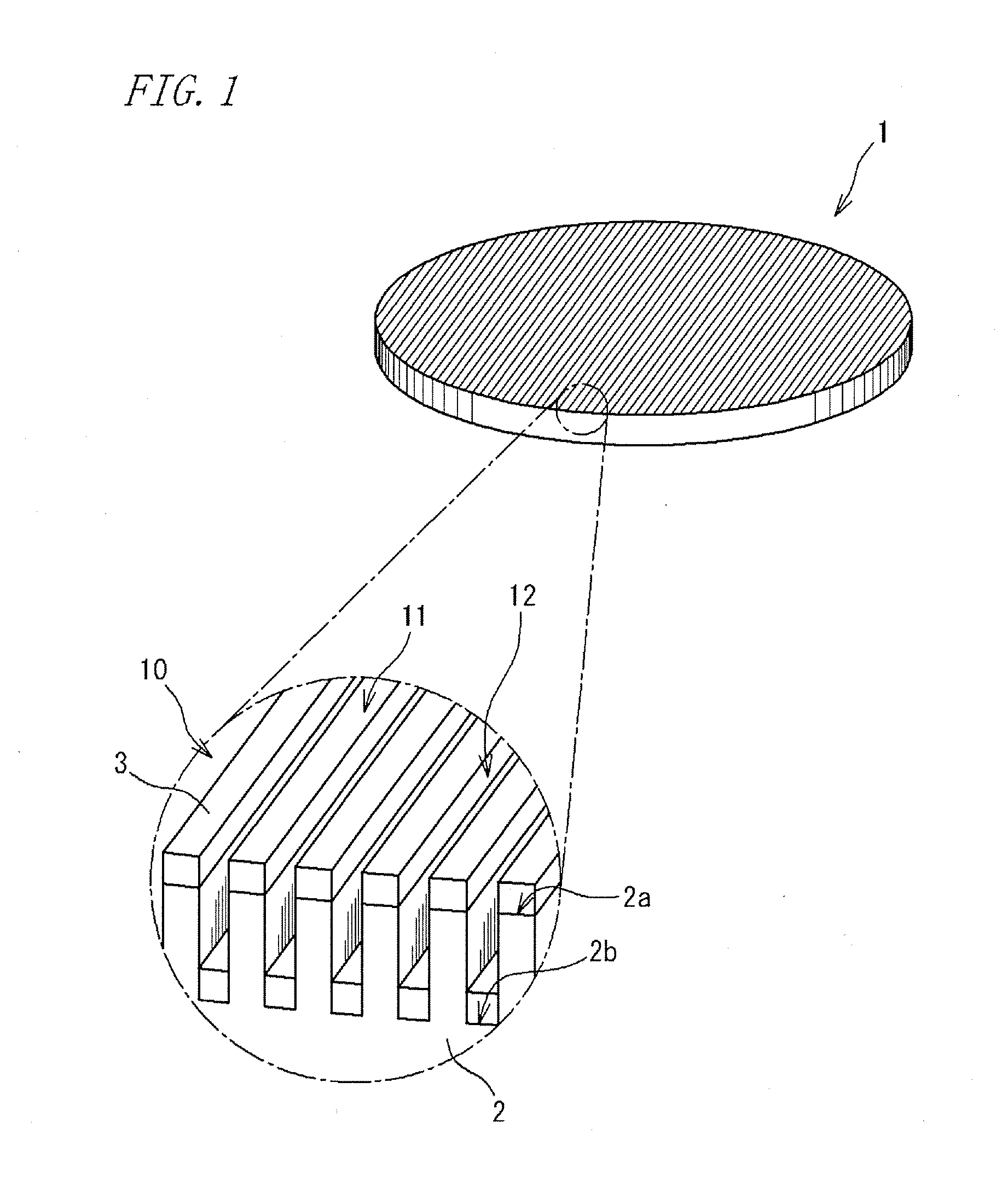
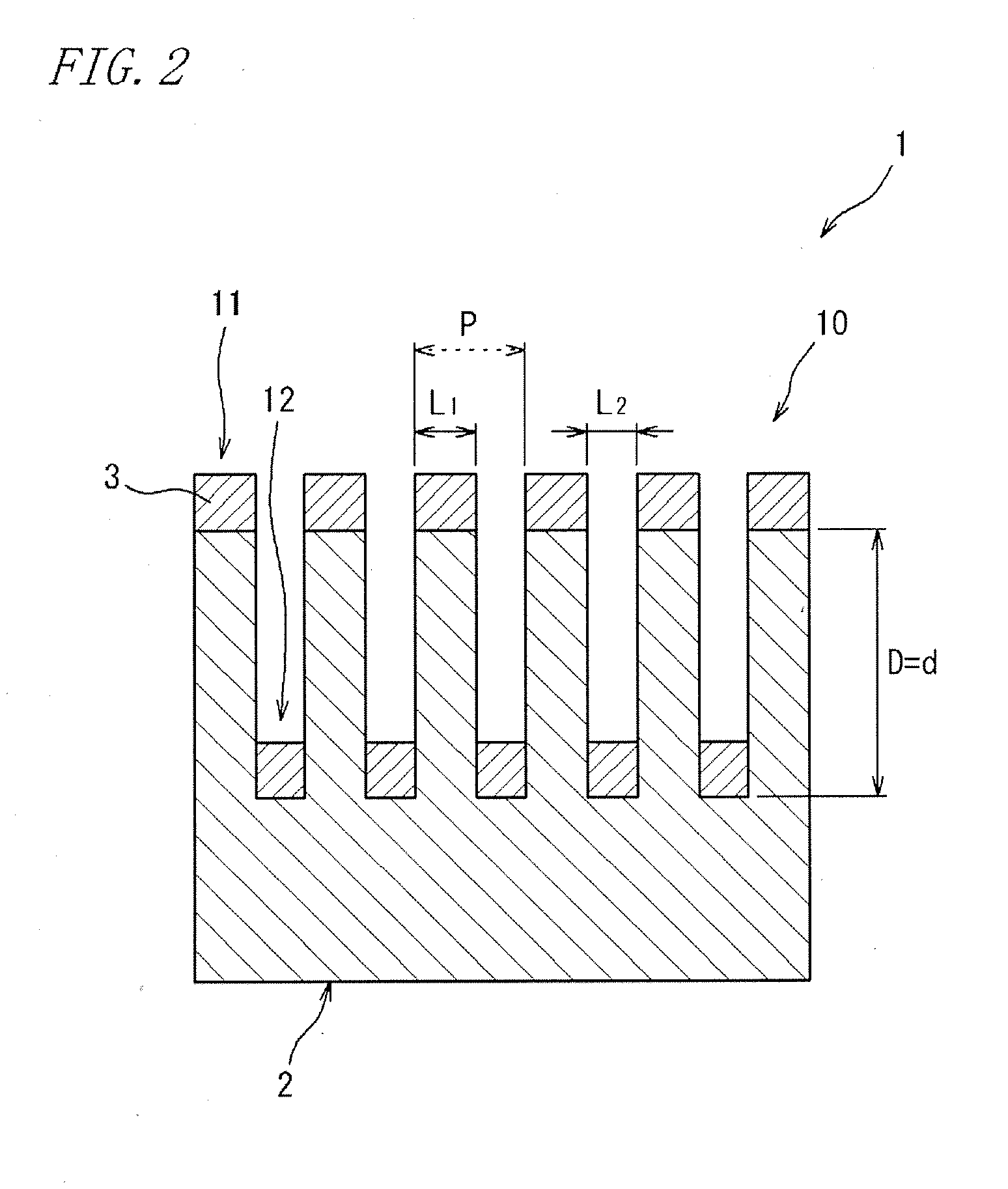
[0036]FIG. 1A is a perspective view illustrating an optical component according to one embodiment (Embodiment 1) of the present invention. FIG. 1B is a perspective view for explaining a main part showing a concave-and-convex structure in the optical component according to Embodiment 1.

[0037]An optical component 1 shown in FIG. 1 is a transmission-type polarization filter that allows carbon dioxide laser light to transmit theret...

embodiment 2

Optical Component

[0049]FIG. 3 is a cross-sectional view for explaining a main part showing a concave-and-convex structure in an optical component according to another embodiment (Embodiment 2) of the present invention. The optical component 1 shown in FIG. 3 is different from the optical component 1 according to Embodiment 1 in that both surfaces of a substrate body 2 have the same concave-and-convex structures 10a and 10b.

[0050]In the optical component 1 according to Embodiment 2, a difference in phase delay between polarization components of the carbon dioxide laser light is proportional to the depth that is the sum of groove depths of groove sections 12a and 12b of respective two concave-and-convex structures 10a and 10b.

[0051]Thus, in order to cause the phase difference that is similar to the one in the case of the optical component 1 according to Embodiment 1 to occur, it is sufficient to form the concave-and-convex structure 10 that has a groove depth of ½ (d / 2) as compared ...

embodiment 3

Optical Component

[0055]FIG. 4 illustrates an optical component according to still another embodiment (Embodiment 3) of the present invention. The optical component 1 of Embodiment 3 shown in FIG. 4 is different from the optical component 1 according to Embodiment 1 in that the optical component 1 of Embodiment 3 shown in FIG. 4 includes two substrate bodies 2a and 2b having the same concave-and-convex structures 10a and 10b, respectively.

[0056]The optical component 1 according to Embodiment 3 includes: a member 1a having a substrate body 2a including the concave-and-convex structure 10a; and a member 1b having a substrate body 2b including the concave-and-convex structure 10b. In the optical component 1 according to Embodiment 3, the substrate bodies 2a and 2b are disposed so that the surfaces thereof are spaced with a predetermined space therebetween and so that the respective concave-and-convex structures 10a and 10b are directed in the same direction.

[0057]Similarly, in the optic...


PUM

PropertyMeasurementUnit
thicknessaaaaaaaaaa
diameteraaaaaaaaaa
depthaaaaaaaaaa

Abstract

At least one surface of a plate member made of ZnSe has a concave-and-convex structure in which a projecting section and a groove section are formed at a spatial cycle equal to or lower than the wavelength of carbon dioxide laser light to thereby provide a substrate body. On a surface of the concave-and-convex structure, an antireflection film is layered that has a lower refractive index than that of ZnSe to carbon dioxide laser light. By this configuration, the polarization state of transmitted carbon dioxide laser light is converted from a linear polarization to a circular polarization or the like.

Description

TECHNICAL FIELD[0001]The present invention relates to an optical component. More particularly, the present invention relates to an optical component for carbon dioxide laser, which is useful for converting carbon dioxide laser light to have a polarization state suitable for the processing of an object to be processed.BACKGROUND ART[0002]Carbon dioxide laser light has been widely used for the processing of an object to be processed because carbon dioxide laser light can easily and stably provide a laser output required for the processing (e.g., cutting) of an object to be processed such as a metal member. Carbon dioxide laser light generated from an oscillator of a carbon dioxide laser processing apparatus is generally linearly polarized. However, when irradiating an object to be processed with this linearly polarized carbon dioxide laser light, a problem in processing quality may occur because a processed width may vary depending on polarization direction of the carbon dioxide laser...

Claims


Application Information

Patent Timeline
Patent Type & Authority Applications(United States)
IPC IPC(8): H01S3/08G02B1/11G02B1/113G02B5/30
CPCB23K26/0639G02B1/115G02B27/4272G02B5/1819G02B27/4261G02B5/1809B23K26/064
Inventor KIKUTA, HISAOKURISU, KENICHIEBATA, KEIJI
Owner PUBLIC UNIVERSITY CORPORATION OSAKA CITY UNIVERSITY
Why Eureka
Try Eureka