Supercharge Your Innovation With Domain-Expert AI Agents!

Approach for prioritizing network alerts

a network alert and priority technology, applied in the field of electric distribution networks, can solve the problems of increasing the number of nodes within the smart grid that experience hardware problems, affecting the reliability of the smart grid, so as to achieve the effect of minimizing the amount of time and being simple and more manageabl

Active Publication Date: 2015-06-30
ITRON NETWORKED SOLUTIONS INC
View PDF1 Cites 0 Cited by
  • Summary
  • Abstract
  • Description
  • Claims
  • Application Information

AI Technical Summary

Benefits of technology

This approach simplifies the handling of crises by aggregating alert information, reducing the time needed to identify the root cause and enabling high-level crisis management, thus improving operational efficiency during network disruptions.

Problems solved by technology

In some situations, a portion of the smart grid may undergo a crisis, during which a large number of nodes within that portion begin to experience hardware problems.
The crisis could be caused by a number of factors, including extreme weather or other hardware-damaging events.
When a crisis occurs and hardware residing in the smart grid becomes compromised, the affected nodes transmit alerts notifying the NOC of the precise nature of the hardware problems.
Problems arise during catastrophic events, when the NOC may receive hundreds or thousands of separate alerts.
Events of significant magnitude may quickly overwhelm the NOC operators, making it difficult to handle or prioritize the alerts in any meaningful way.
Consequently, NOC operators can have quite a bit of difficultly reacting to and managing such events quickly and effectively, which, among other things, can have a substantial negative impact on quality of service.

Method used


Image

  • Approach for prioritizing network alerts
  • Approach for prioritizing network alerts
  • Approach for prioritizing network alerts

Examples


Embodiment Construction

[0020]In the following description, numerous specific details are set forth to provide a more thorough understanding of the present invention. However, it will be apparent to one of skill in the art that the present invention may be practiced without one or more of these specific details. In other instances, well-known features have not been described in order to avoid obscuring the present invention.

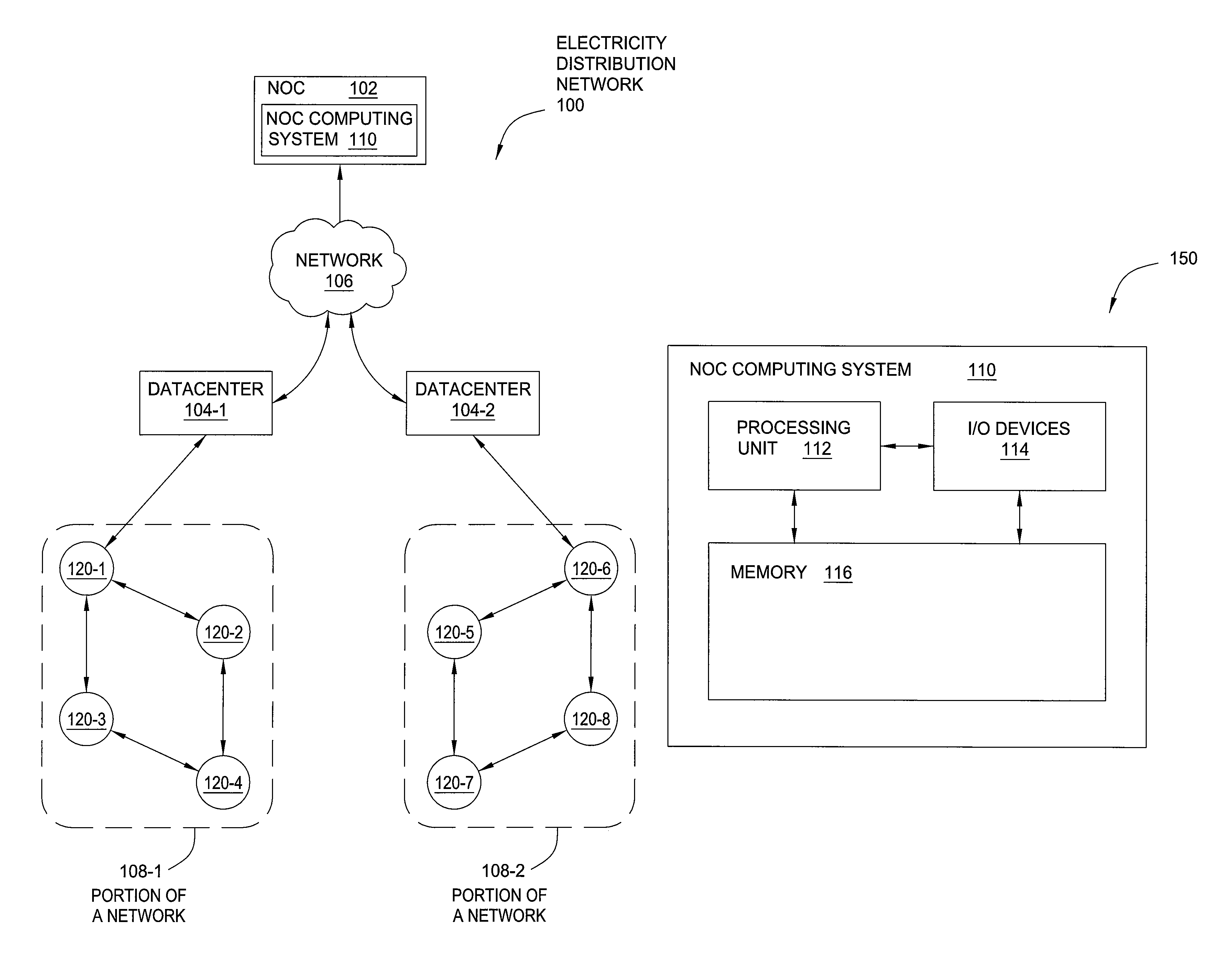
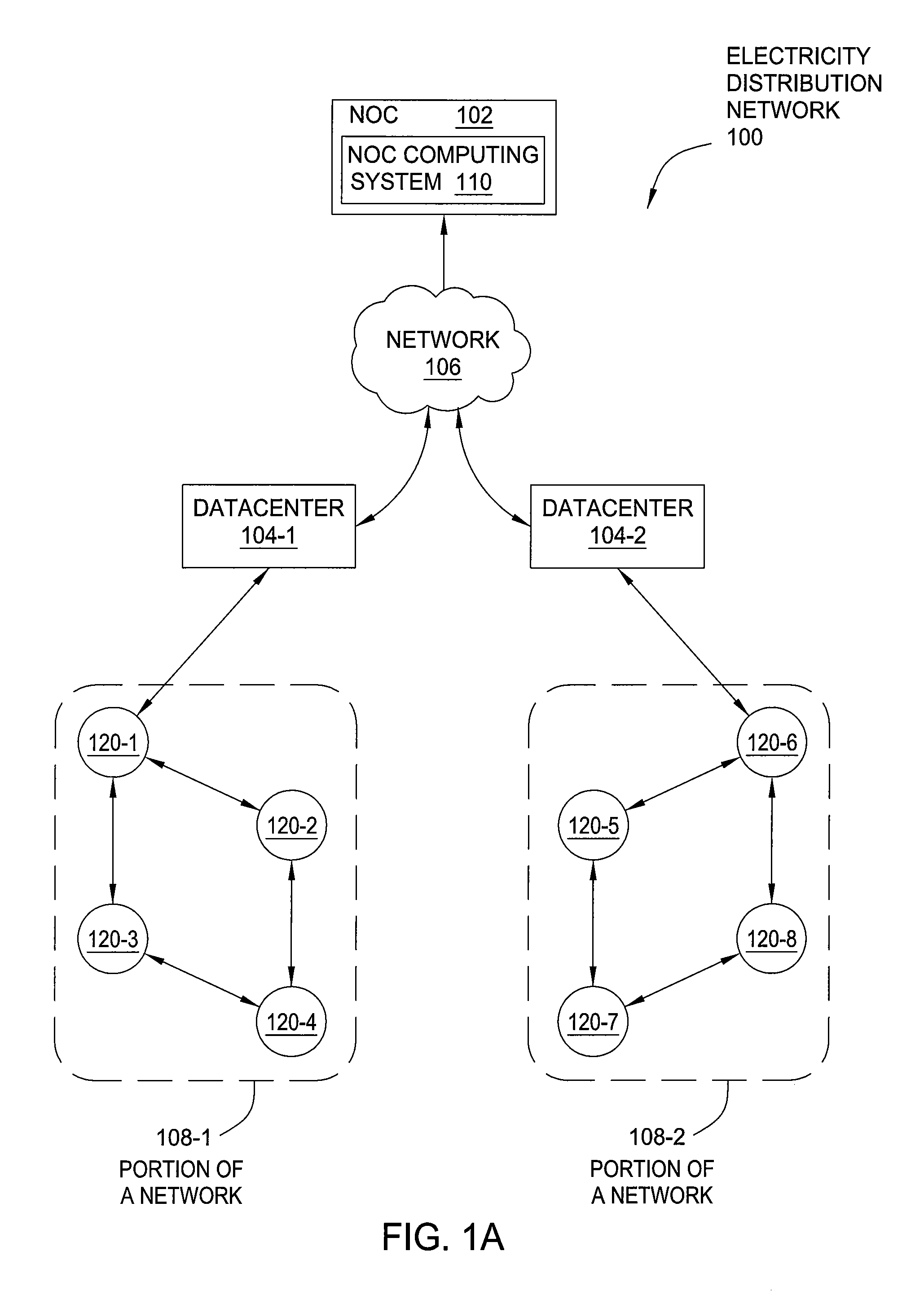
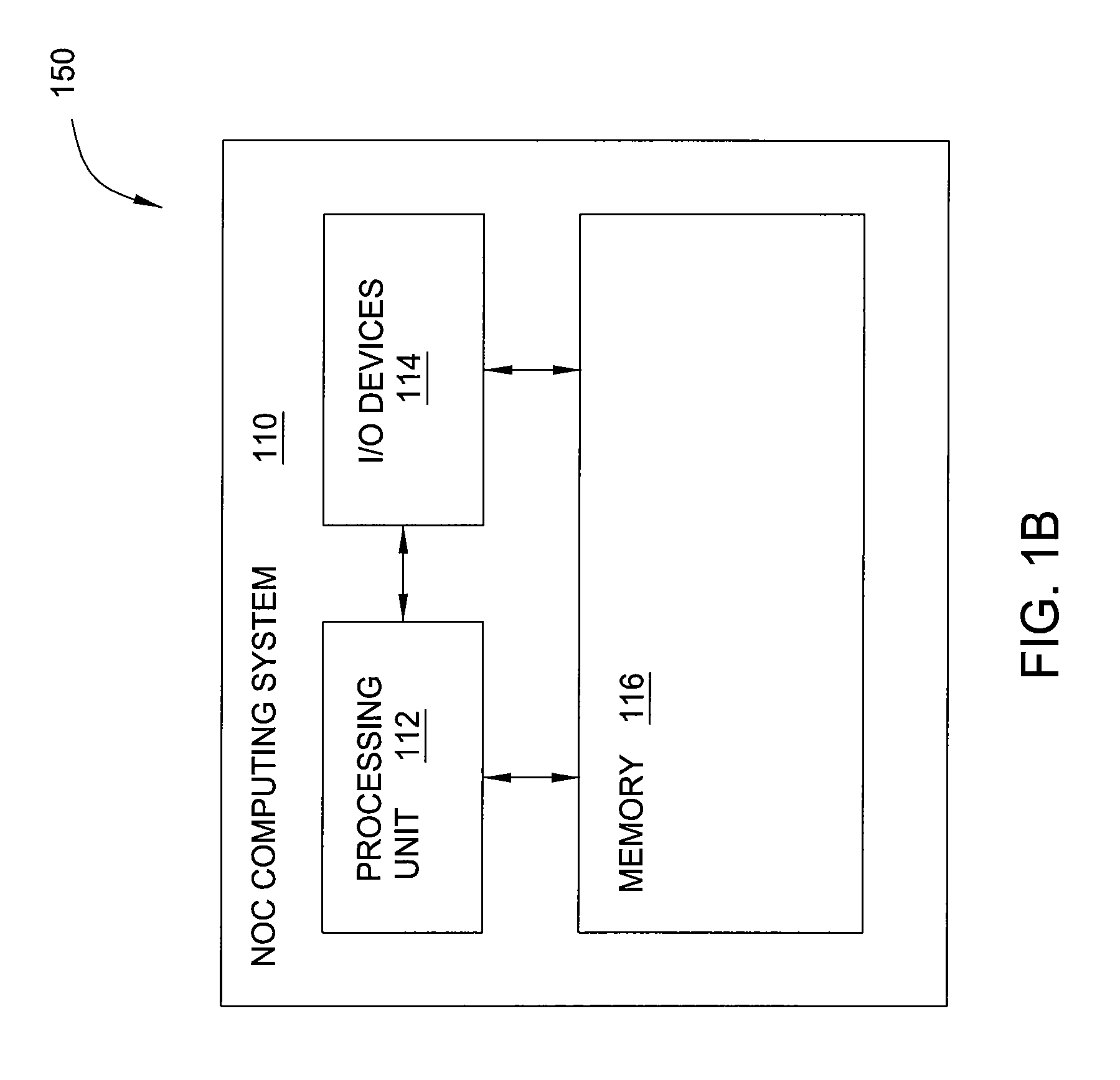
[0021]FIG. 1A illustrates an electricity distribution network 100 configured to implement one or more aspects of the present invention. As shown, electricity distribution network 100 includes a network operations center (NOC) 102 coupled to datacenters 104-1 and 104-2 via a network 106. Datacenters 104 are in turn coupled to portions of a network 108-1 and 108-2. Each of the portions of a network 108 represent a different portion of a computer-controlled electricity distribution infrastructure, referred to herein as a “smart grid.” Portions of a network 108 could represent portions of t...


PUM


Abstract

A computing system receives status transmissions from nodes within a portion of an electricity distribution network. The status transmissions include information related to hardware problems experienced by nodes within the portion of that network. The computing system determines a “heat” value for each of the status transmissions, where the heat value for a given transmission represents the operating conditions of, and / or the severity of hardware / software problems experienced by, the node responsible for sending that transmission. The computing system aggregates the heat values across the entire portion of the electricity distribution network and compares the aggregated heat values to a threshold value. When the aggregated value exceeds the threshold value, the computing system identifies a crisis situation arising within the portion of the electricity distribution network. The computing system may then convey information associated with the status transmissions to operators of the electricity distribution network.

Description

CROSS-REFERENCE TO RELATED APPLICATIONS[0001]This application claims benefit of U.S. provisional patent application Ser. No. 61 / 598,546, filed Feb. 14, 2012, which is hereby incorporated herein by reference.BACKGROUND[0002]1. Field of the Invention[0003]Embodiments of the present invention relate generally to electricity distribution networks and, more specifically, to an approach for prioritizing network alerts.[0004]2. Description of the Related Art[0005]A network operations center (NOC) is a centralized control station that observes and operates an electricity distribution infrastructure, such as a “smart grid.” A smart grid includes a set of interconnected nodes that participate in managing and distributing electricity to consumers. Each node in the smart grid includes a particular type of hardware and performs a given task based on that type of hardware. A given node also includes a monitor that supervises the operation of the hardware within the node and reports status informa...

Claims


Application Information

Patent Timeline
Patent Type & Authority Patents(United States)
IPC IPC(8): G08B23/00G06Q10/10G06Q50/06H02J13/00
CPCG06Q10/1093G06Q50/06H02J13/0086H02J13/00028
Inventor BARNES, JAMES
Owner ITRON NETWORKED SOLUTIONS INC
Features
  • R&D
  • Intellectual Property
  • Life Sciences
  • Materials
  • Tech Scout
  • Unparalleled Data Quality
  • Higher Quality Content
  • 60% Fewer Hallucinations
Learn More