Improving the depth of field in an imaging system

a technology of depth of field and imaging system, which is applied in the field of improving the depth of field in the imaging system, can solve the problems of reducing the camera's performance in low light, reducing the shutter speed by a factor of 4 or 8 and the limitation that exists in all optical systems used in cameras today

Inactive Publication Date: 2015-07-07
DUAL APERTURE INT
View PDF22 Cites 8 Cited by
  • Summary
  • Abstract
  • Description
  • Claims
  • Application Information

AI Technical Summary

Benefits of technology

[0009]It is an object of the invention to reduce or eliminate at least one of the drawbacks known in the prior art and to provide in a first aspect of the invention a method of capturing an image. The method comprises the steps of: exposing an image sensor to radiation from a first part of the electromagnetic spectrum using a first aperture and to radiation from a second part of the spectrum using a second aperture having a different size than the first aperture; and, forming an image on the basis of first image data generated by the radiation from the first part of the spectrum and second image data generated by radiation from the second part of the spectrum.
[0010]By exposing an image sensor with radiation from two different apertures the DOF of the optical system can be improved in an very simple way. The method allows a fixed focus lens to have a relatively wide aperture, hence effectively operating in lower light situations, while at the same time providing a greater DOF resulting in sharper pictures. Further, the method effectively increase the optical performance of lenses, reducing the cost of a lens required to achieve the same performance.
[0011]In one embodiment the image sensor is simultaneously exposed by radiation from the first and second aperture. One exposure of the image sensors allows efficient capturing of both small aperture and large aperture image information thus reducing effects of motion blur which occur when using conventional techniques like focus stacking.
[0012]In another embodiment the method further comprising the steps of: subjecting the first image data to a high pass filter; adding the filtered high frequency components of the first image data to the second image data. Using this embodiment, the sharp image information can be easily accessed via the high-frequency information produced by the small aperture image data.
[0014]In a further embodiment the image sensor used in the method comprises a pixel array coupled to a filter array, each filter in the filter array being adapted to pass radiation of a part of the spectrum and wherein the filter array comprising one or more color filters configured to pass radiation in a color band and / or one or more infra-red filters configured to reflect visible radiation and to transmit infra-red radiation. The filter array may be easily optimized for a particular aperture configuration.
[0018]Thin film technology allow easy adaptation of the optical characteristics of the aperture system. In one embodiment, at least one of the filters is configured as a tunable filter comprising dielectric layers arranged between polymer layers, wherein the polymer layers serve as elastic springs and wherein the thickness between the dielectric layers is controlled by applying a voltage to the multi-layered system. In another embodiment, at least one aperture of the aperture system is configured as an adjustable aperture, the adjustable aperture comprising a hole in a sheet of an electro-active material wherein the size (diameter) of the hole is controlled by applying a voltage over the sheet.

Problems solved by technology

A limitation that exists in all optical systems used in cameras today is the tradeoff between aperture and the depth of field (DOF).
This tradeoff reduces the camera's performance in low light situations typically reducing the shutter speed by a factor of 4 or 8.
Further, in low light applications a wide aperture is required, which results in a loss of DOF.
Wide aperture lenses require greater precision for optical performance and are therefore expensive.
Moreover, as the focus stacking requires multiple images taken at subsequent moments in time this technique is sensitive to motion blur.
The aperture splitting mirror however is complex to fabricate and produces high optical aberrations.
Moreover, implementation of such splitting mirror in a camera requires a relative complex optical system which requires precise alignment.

Method used


Image

  • Improving the depth of field in an imaging system
  • Improving the depth of field in an imaging system
  • Improving the depth of field in an imaging system

Examples


Embodiment Construction

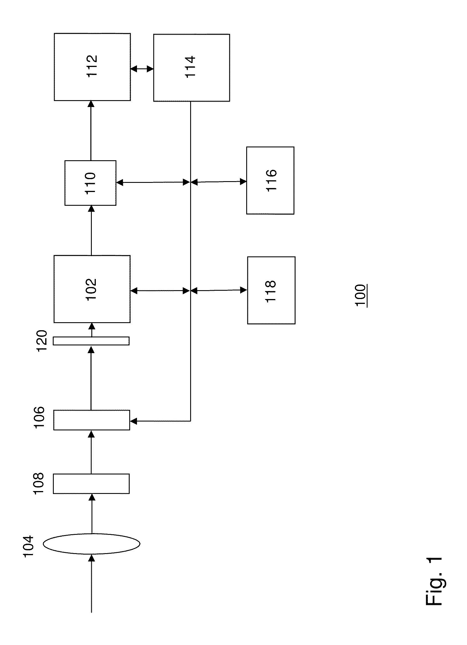
[0026]FIG. 1 illustrates an imaging system 100 according to one embodiment of the invention. The imaging system comprises an image sensor 102, a lens system 104 for focusing objects in a scene onto the imaging plane of the image sensor, a shutter 106 and an aperture system 108 with two or more apertures for allowing radiation into the imaging system. The imaging system may be part of a digital camera or integrated in a mobile phone, a webcam and other multimedia devices requiring image capturing functionality.

[0027]The shutter may be a mechanical shutter or, alternatively, the shutter may be an electronic shutter integrated in the image sensor. The image sensor comprises rows and columns of photosensitive sites (pixels) forming a two dimensional pixel array. The image sensor may be an CMOS (Complimentary Metal Oxide Semiconductor) active pixel sensor or an CCD (Charge Coupled Device) image sensor.

[0028]When the radiation is projected by the lens system onto the image sensor, each pi...


PUM


Abstract

A method is described of capturing an image. The method comprising the steps of: exposing an image sensor to radiation from a first part of the electromagnetic spectrum using a first aperture and to radiation from a second part of the spectrum using a second aperture having a different size than the first aperture; and, forming an image on the basis of first image data generated by the radiation from the first part of the spectrum and second image data generated by radiation from the second part of the spectrum.

Description

PRIORITY CLAIM TO RELATED APPLICATIONS[0001]This application is a national stage application under 35 U.S.C. §371 of PCT / EP2009 / 050502, filed 16 Jan. 2009, published as WO 2010 / 081556 A1 on 22 Jul. 2010.FIELD OF THE INVENTION[0002]The invention relates to improving the depth of field in an imaging system, and, in particular, though not exclusively, to a method for capturing an image having an improved depth of field, and an imaging system using such method.BACKGROUND OF THE INVENTION[0003]A limitation that exists in all optical systems used in cameras today is the tradeoff between aperture and the depth of field (DOF). An aperture determines the amount of light that enters the camera and the DOF determines the range of distances from the camera that are in focus when the image is captured. The wider the aperture (the more light received) the more limited the DOF.[0004]In many applications the tradeoff between aperture and the DOF becomes apparent. For example, most mobile phones hav...

Claims


Application Information

Patent Timeline
Patent Type & Authority Patents(United States)
IPC IPC(8): H04N5/335H04N1/409H04N5/33H04N5/225
CPCH04N5/33H04N1/409H04N25/131H04N25/135H04N25/58H04N25/617
Inventor WAJS, ANDREW AUGUSTINE
Owner DUAL APERTURE INT
Why Eureka
Try Eureka