T-sensor devices and methods of using same

Active Publication Date: 2015-07-21
ENTANGLEMENT TECH
View PDF2 Cites 0 Cited by
  • Summary
  • Abstract
  • Description
  • Claims
  • Application Information

AI Technical Summary

Benefits of technology

[0012]Fluid T-sensors according to the invention are particularly useful when the sensor(s) utilized therein are sensors utilized in cavity enhanced absorption spectroscopy (e.g., cavity ring-down spectroscopy). Such T-sensors comprise one or more optical

Problems solved by technology

However, the sensing method often is spatially sparse, for example because of resource limitations.
A limited numbe

Method used


Image

  • T-sensor devices and methods of using same
  • T-sensor devices and methods of using same
  • T-sensor devices and methods of using same

Examples


Example

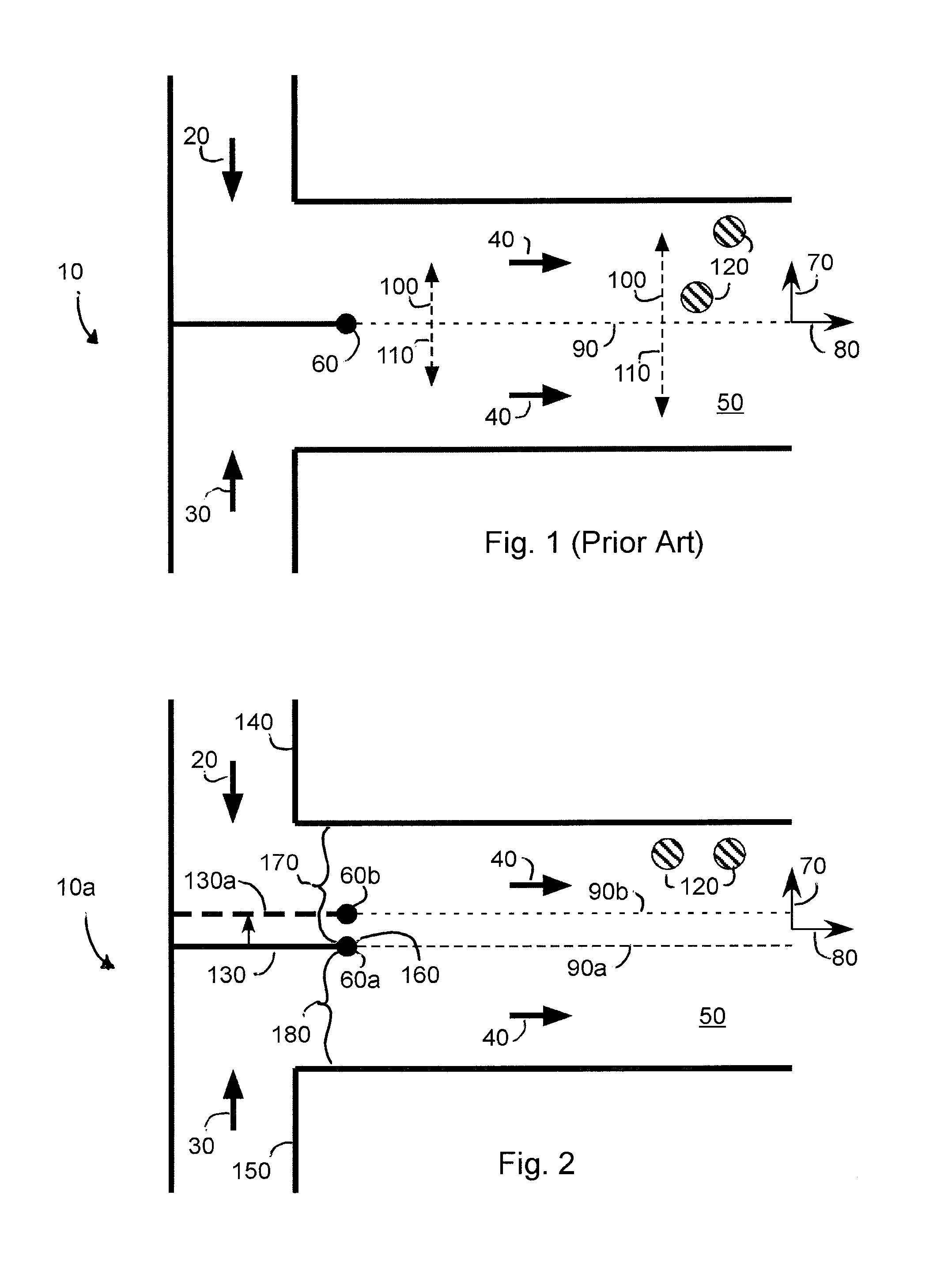
[0025]FIG. 2 is a schematic representation of a T-sensor 10a according to an embodiment of the invention having a limited number of sensing locations 120 and two joined flows 20, 30 with a laterally movable but longitudinally fixed divider 130 between the two input flows (reference numbers for similar elements in the T-sensor shown in FIG. 1 also appear in FIG. 2). An input fluid (e.g., Fluid A—see arrow 20) flows into the T-sensor through a first supply conduit 140. A second input fluid (e.g. Fluid B—see arrow 30) flows into the T-sensor through a second supply conduit 150. The first fluid and the second fluid are separated from each other by the divider 130. The end of the divider 160 where the two fluids first contact each other is defined as an initial diffusion start point 60a. It will be appreciated that FIG. 2 depicts the T-sensor in only two-dimensions (i.e., the plane defined by the paper on which FIG. 2 is drawn) and thus the end of the divider 160 appears in FIG. 2 as a p...


PUM


Abstract

T-sensor devices that include a main conduit that defines a diffusion space, at least a first and second supply conduit for conveying fluids into the main conduit, and at least one sensor having a sensing zone that extends into the diffusion space in a fixed location relative to the main conduit. The first and second supply conduits are separated by divider from which a diffusion interface extends into the diffusion space. In order to capture sensing information without employing moving the physical location of sensors or employing more sensors, devices according to the invention alter a location of a diffusion interface extending into the diffusion space from a diffusion start point on the divider relative to the sensing zone of the at least one sensor, without altering the fixed location of the sensor relative to the main conduit. Methods of sensing properties of fluids and analytes are also disclosed.

Description

CROSS-REFERENCE TO RELATED APPLICATIONS[0001]This application is a continuation-in-part of co-pending U.S. application Ser. No. 13 / 485,391, filed May 31, 2012, which claims priority to U.S. Provisional Application Ser. No. 61 / 520,111, filed Jun. 3, 2011.BACKGROUND OF INVENTION[0002]1. Field of Invention[0003]The present invention relates to fluid T-sensors. More particularly, the present invention relates to fluid T-sensors that are capable of altering a location of a diffusion interface between at least two fluids flowing in a diffusion space within a main conduit relative to a sensing zone of at least one sensor that is fixed relative to the main conduit without altering the fixed location of the at least one sensor relative to the main conduit.[0004]2. Description of Related Art[0005]H-filters were developed in the late 1990's. In their simplest form, H-filters combine two or more fluid flows into a combined, side-by-side, laminar flow stream. Over the length of the filter, speci...

Claims


Application Information

Patent Timeline
IPC IPC(8): G01N30/00
CPCG01N30/0005
Inventor RICHMAN, BRUCE A.MILLER, ANTHONY
Owner ENTANGLEMENT TECH
Why Eureka
Try Eureka