System for dissolving gases in fuel

Inactive Publication Date: 2013-07-25
HELPFUL TECH
View PDF25 Cites 0 Cited by
  • Summary
  • Abstract
  • Description
  • Claims
  • Application Information

AI Technical Summary

Benefits of technology

This patent describes a system for gasifying liquid fuel using an absorber, a vortex reactor, an evacuation tube, and a reservoir. The system is designed to allow gas to be dissolved into liquid fuel, creating a gas / fuel solution that can be used in an engine. The system can gasify a variety of liquid fuels and gas sources, such as air, oxygen, carbon dioxide, combustion exhaust, or natural gas. The technical effects of this system include increased efficiency and reduced emissions in the gasification process, improved fuel quality, and improved engine performance.

Problems solved by technology

In practice it is difficult to satisfy both of these requirements simultaneously, and the achieved effect is not stable at varying loads.

Method used


Image

  • System for dissolving gases in fuel
  • System for dissolving gases in fuel
  • System for dissolving gases in fuel

Examples


Embodiment Construction

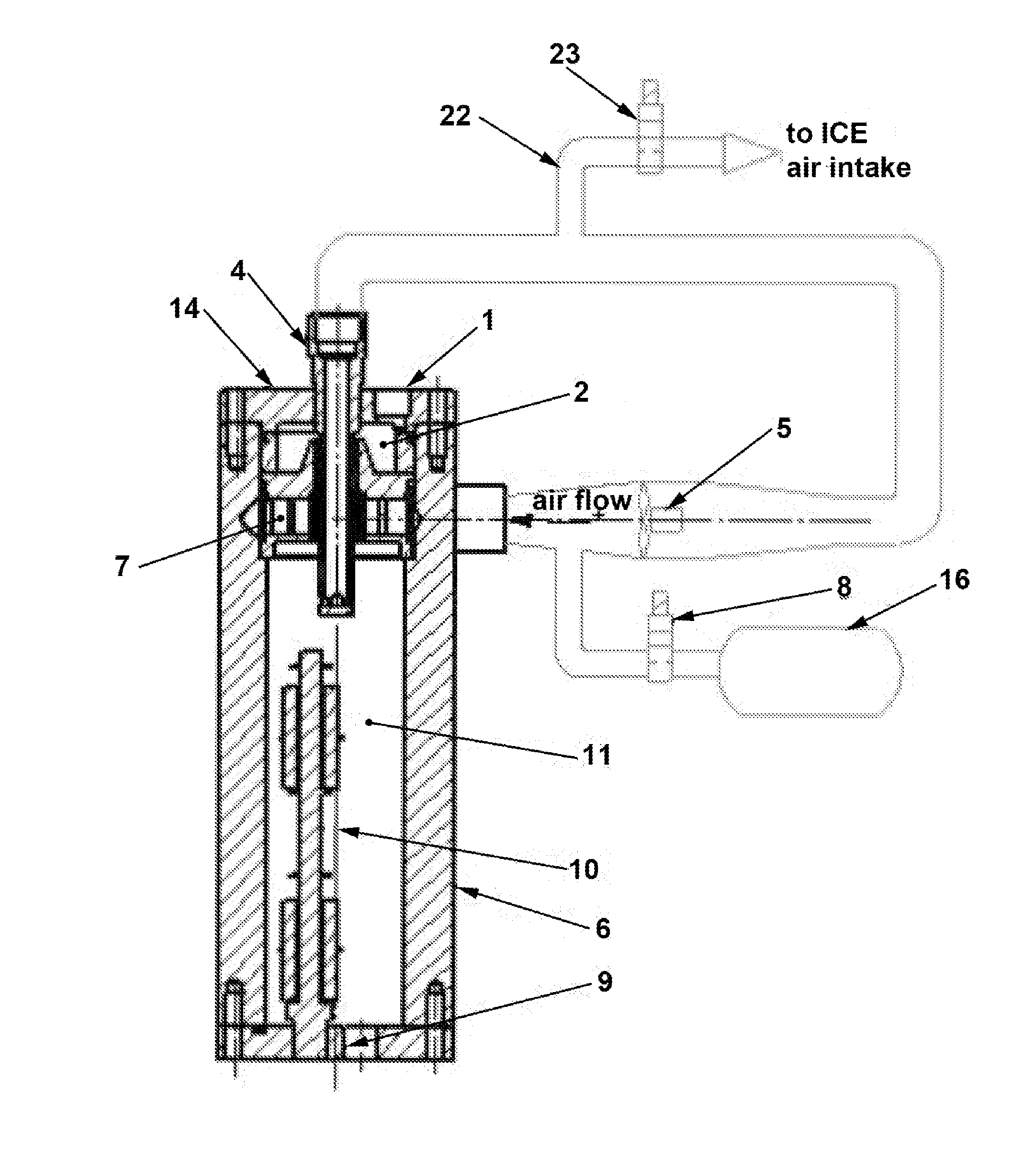
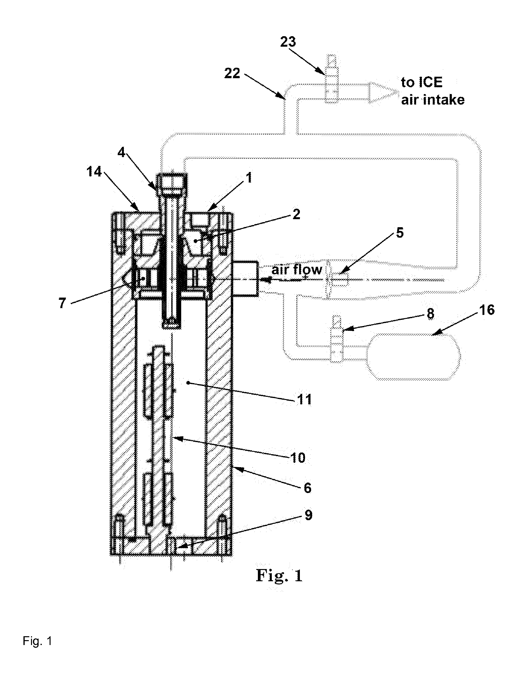
[0016]Referring to the drawing figures, a liquid fuel absorber apparatus includes a cylindrical absorber body 6 with a tangential inlet port 12 through the body wall into its interior chamber. The flow axis of the tangential inlet port 12 coincides with the central horizontal plane of a vortex reactor 7. Gas entering the reactor 7 at high speed passes through swirl vanes 13 generating a gas vortex within the absorber 6.

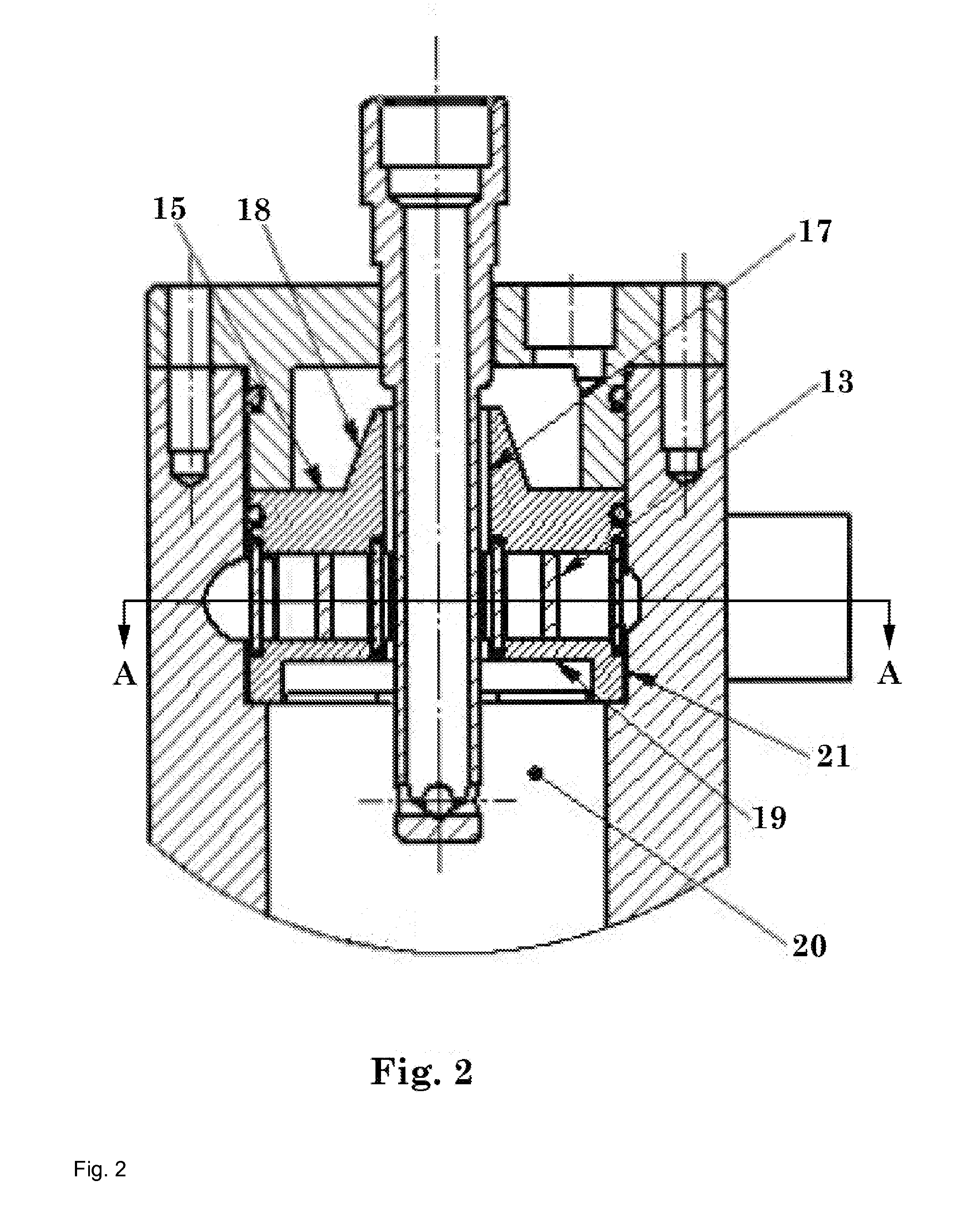
[0017]Engine fuel passes through an inlet port 1 in the top cap 14 of the absorber body 6, into a fuel space 2 between the top cap 14 and vortex reactor top plate 15. The top plate 15 has a raised border 18 around its central bore. Fuel from the fuel space 2 overflowing this raised border 18“leaks” through the thin annular gap 17 between the raised border 18 and an evacuating tube 4 (which extends from within the absorber body 6) to the middle of the vortex reactor 7, where gas from the swirl vanes 13 creates the vortex around the evacuating tube 4. This vortex disper...


PUM


Abstract

A system for gasification of liquid fuel includes an absorber to receive liquid fuel and as through separate ports, a vortex reactor to create a vortex of the gas and fuel droplets to enhance absorption of gas into the fuel, and a recirculation loop to remove and recirculate unabsorbed gas and fuel vapors from the absorber back to its tangential inlet port. Gasified fuel collects at the bottom of the absorber for delivery to an engine.

Description

CROSS-REFERENCE TO RELATED APPLICATION[0001]This is a continuation of International Application PCT / US2013 / 22575 with an international filing date of Jan. 22, 2013, which is co-pending with Provisional Application No. 61 / 589,363 filed on Jan. 22, 2012, the contents of which are incorporated herein by reference thereto.FIELD OF THE INVENTION[0002]The system of this invention relates to treatment of fuel for internal combustion engines, and more specifically to gasification of such fuel for improved combustion.BACKGROUND OF THE INVENTION[0003]Methods and means for dissolving gases into liquid fuel for an engine combustion chamber are known in the prior art. One method is to dissolve gas at high pressure into a thin film of fuel. It was described in U.S. Pat. No. 7,011,048 dated Mar. 14, 2006. Another method is to direct high pressure gas into the smallest possible droplets of liquid fuel. The use of nozzles to disperse fuel is described in Russian Pat. 2129662 dated Feb. 2, 1998, U.S....

Claims


Application Information

Patent Timeline
IPC IPC(8): F02M29/00B01F3/04
CPCF02M29/00Y02T10/32F02M21/045Y02T10/30
Inventor GURIN, VICTORMACIJAUSKAS, MINDAUGASPERMIAKOV, SERGUEIPIKUL, PAVELGOLTSMAN, MARK
Owner HELPFUL TECH
Why Eureka
Try Eureka