Illumination system and illumination method

a technology of illumination system and illumination method, which is applied in the direction of process control, instruments, applications, etc., can solve the problems of reducing detection accuracy, reducing the emission efficiency of light source device, and reducing the detection accuracy, so as to achieve the effect of increasing the size of the light source device and not decreasing the emission efficiency

Active Publication Date: 2015-07-21
OLYMPUS CORP
View PDF9 Cites 0 Cited by
  • Summary
  • Abstract
  • Description
  • Claims
  • Application Information

AI Technical Summary

Benefits of technology

[0009]The present invention is made in view of the above circumstances and an object thereof is to provide an illumination system and an illumination method capable of detecting abnormalities of a light source device without decreasing emission efficiency and without increasing the light source device in size.

Problems solved by technology

Accordingly, losses of excitation light from the light source toward the optical component increase, leading to lower emission efficiency of the light source device.
In addition, detection items that can be detected by reflected light are limited, which decreases detection accuracy.

Method used


Image

  • Illumination system and illumination method
  • Illumination system and illumination method
  • Illumination system and illumination method

Examples


Embodiment Construction

[0020]The embodiments of the present invention will be described below in detail with reference to the drawings.

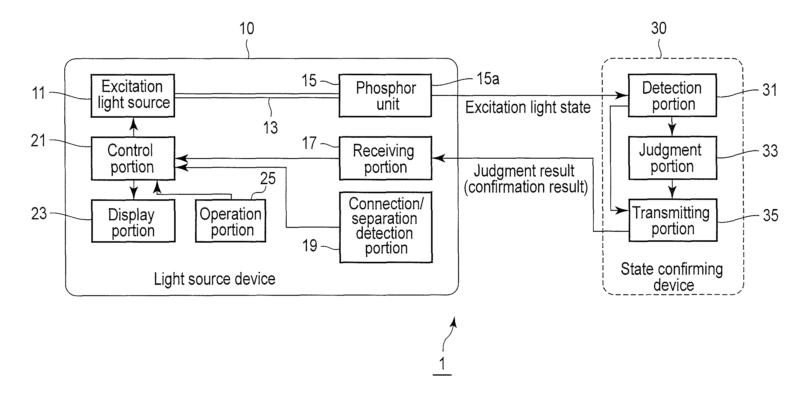
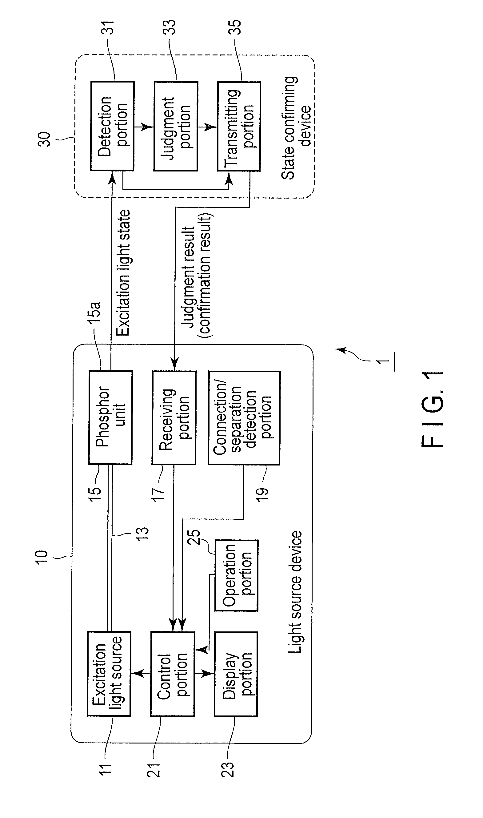
[0021]The first embodiment will be described with reference to FIGS. 1, 2, 3A, and 3B. An operation method in the present embodiment is executed in the order of the state confirming step, illumination permission step, and illumination step.

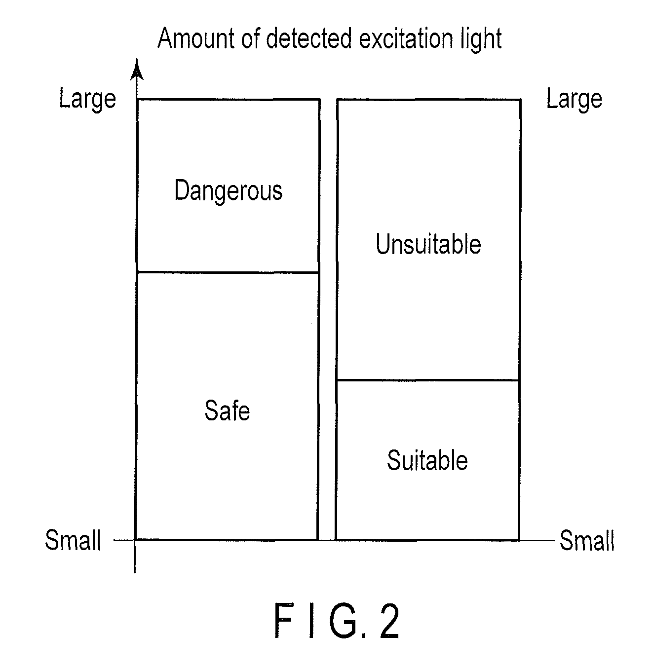
[0022]The state confirming step indicates that the state of a light source device 10 is confirmed by a state confirming device 30 described later.

[0023]The illumination permission step indicates preparation processing to proceed to the illumination step and also indicates processing to permit the execution of the illumination step when the state confirming device 30 confirms that the light source device 10 has no abnormal condition in the state confirming step.

[0024]The illumination step indicates that an excitation light source 11 emits excitation light so that the light source device 10 illuminates an illuminated object (not shown) whe...


PUM


Abstract

An illumination system includes an excitation light source that emits excitation light, a phosphor unit that converts the excitation light emitted from the excitation light source into fluorescence to emit the fluorescence toward an illuminated object and a light source device including the excitation light source and the phosphor unit. The illumination system further includes a state confirming device that confirms a state of the light source device based on the state of the phosphor unit when connected to the light source device and the phosphor unit emits the fluorescence.

Description

CROSS REFERENCE TO RELATED APPLICATIONS[0001]This application is a Continuation Application of PCT Application No. PCT / JP2011 / 070167, filed Sep. 5, 2011 and based upon and claiming the benefit of priority from prior Japanese Patent Application No. 2010-222841, filed Sep. 30, 2010, the entire contents of all of which are incorporated herein by reference.BACKGROUND OF THE INVENTION[0002]1. Field of the Invention[0003]The present invention relates to an illumination system and an illumination method that illuminate an illuminated object.[0004]2. Description of the Related Art[0005]For example, Jpn. Pat. Appln. KOKAI Publication No. 2008-26698 discloses a luminescent device as a light source device having a configuration capable of detecting a broken wire with high accuracy. The light source device includes a light source, a lens, a connector, a light guiding member, and an optical component. The light source includes a semiconductor light-emitting device that emits light, for example, ...

Claims


Application Information

Patent Timeline
Patent Type & Authority Patents(United States)
IPC IPC(8): A61B1/06G05D25/02H05B37/02H05B33/08H05B44/00
CPCH05B37/0209G05D25/02H05B33/089H05B47/10H05B47/20
Inventor NISHIO, MASAHIRO
Owner OLYMPUS CORP
Why Eureka
Try Eureka