Wall construction system, wall stud, and method of installation

a construction system and wall technology, applied in the direction of structural elements, building components, load-supporting elements, etc., can solve the problems of steel frame prone to rusting, difficult to handle panels, and prone to distortion, so as to facilitate the construction of concrete walls, reduce the weight of formwork structures, and prevent twisting and shear movement of panels

Inactive Publication Date: 2015-07-28
SAFARI HEIGHTS
View PDF33 Cites 3 Cited by
  • Summary
  • Abstract
  • Description
  • Claims
  • Application Information

AI Technical Summary

Benefits of technology

[0008]According to one aspect of the present invention there is provided a wall stud for positioning between an opposing pair of formwork boards. The wall stud includes a body, a plurality of ribs and two side walls located on opposing sides of the body, each side wall having an inner face and an outer face. The stud body has at least one opening adapted to receive at least one reinforcing rod, thereby advantageously accurately holding the reinforcing rods in place. The stud body is positioned approximately in the centre of the inner face of each side wall so that a horizontal cross-section of the stud is substantially an H shape. Each of the plurality of ribs is located between the two side walls on a side of the body substantially perpendicular to the body. The outer faces of the side walls are securable to a said formwork board.
[0013]The wall stud and stud joiner clip are preferably formed from a polymer material such as plastic, or other such material. This advantageously makes the wall stud and stud joiner clip light weight, easy to install, very rigid and ensures they will not rust or corrode.
[0017]The wall construction installation according to the present invention advantageously reduces the weight of the formwork structure, ensures accurate placement of horizontal and vertical reinforcing bars and because of their rigid structure prevent distortion, twisting and shear movement of the panels, facilitating construction of the concrete wall.

Problems solved by technology

Aluminium and steel stud frames have the disadvantage of being heavy making the panels difficult to handle.
Panels are also prone to distortion due to the flexibility of the studs.
In addition, the steel frames can be prone to rusting as the outer edge of the steel studs are not covered by concrete, only by the formwork wall board sheet.
Further, the aluminium frames can corrode when in contact with concrete.
Operators using this system often misalign or incorrectly place the box shaped spacers making it difficult to place the reinforcing bars in the formwork.
Further, due to this wall construction system requiring a disposable template for the accurate positioning of box spacers, the system is difficult to automate.

Method used


Image

  • Wall construction system, wall stud, and method of installation
  • Wall construction system, wall stud, and method of installation
  • Wall construction system, wall stud, and method of installation

Examples


Embodiment Construction

[0031]Embodiments of the method of wall construction, the wall stud, and wall stud assembly, including a stud joiner clip will now be described with reference to the accompanying drawings.

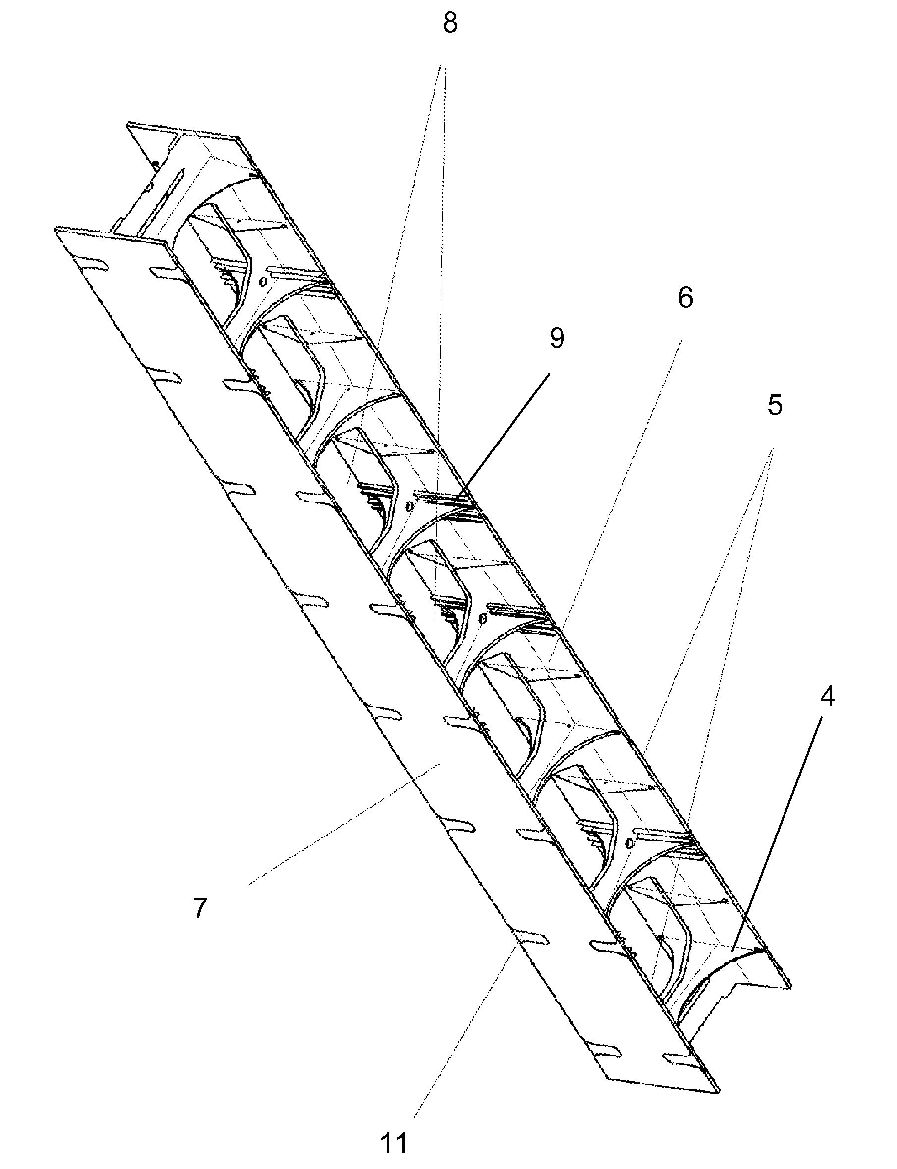
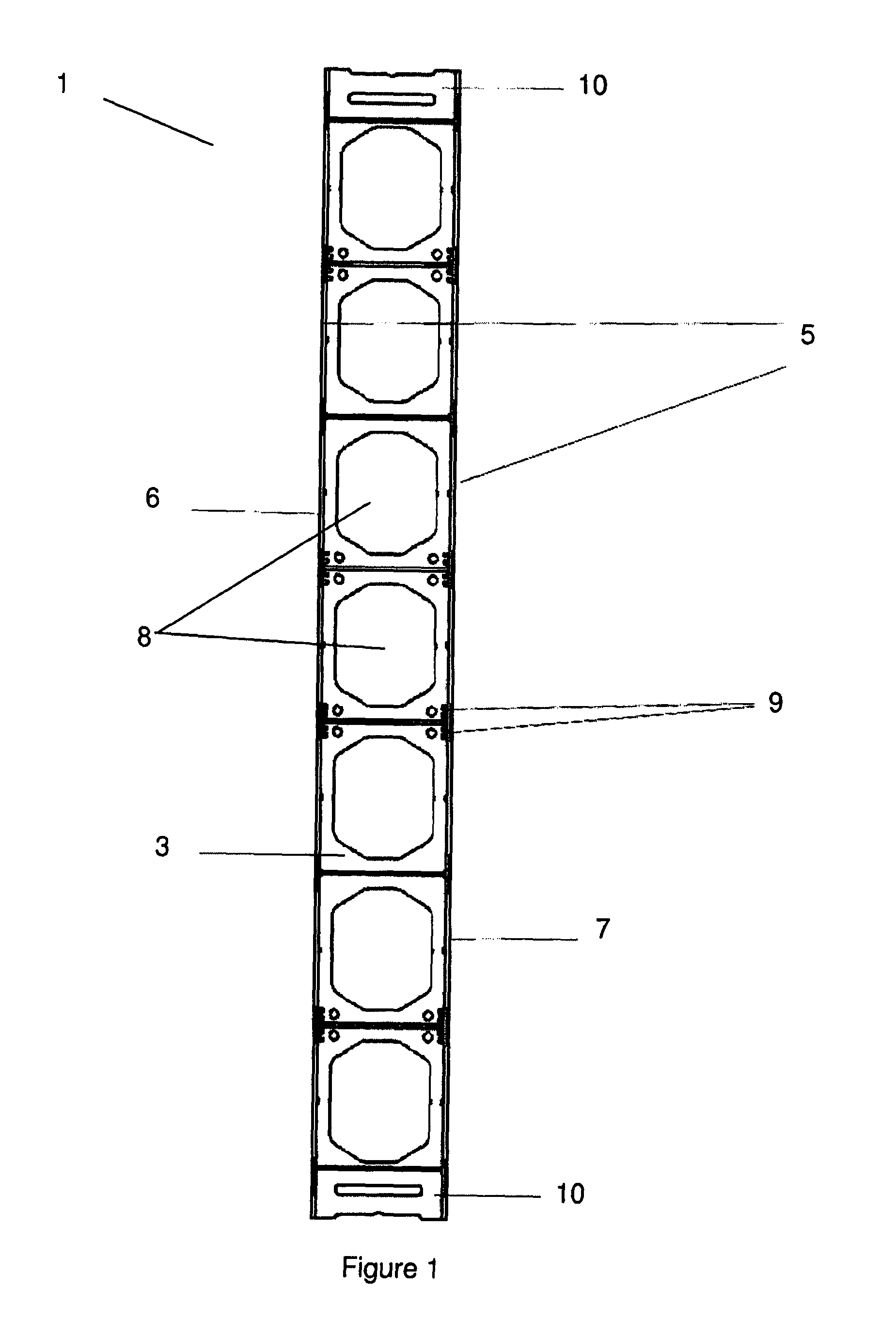
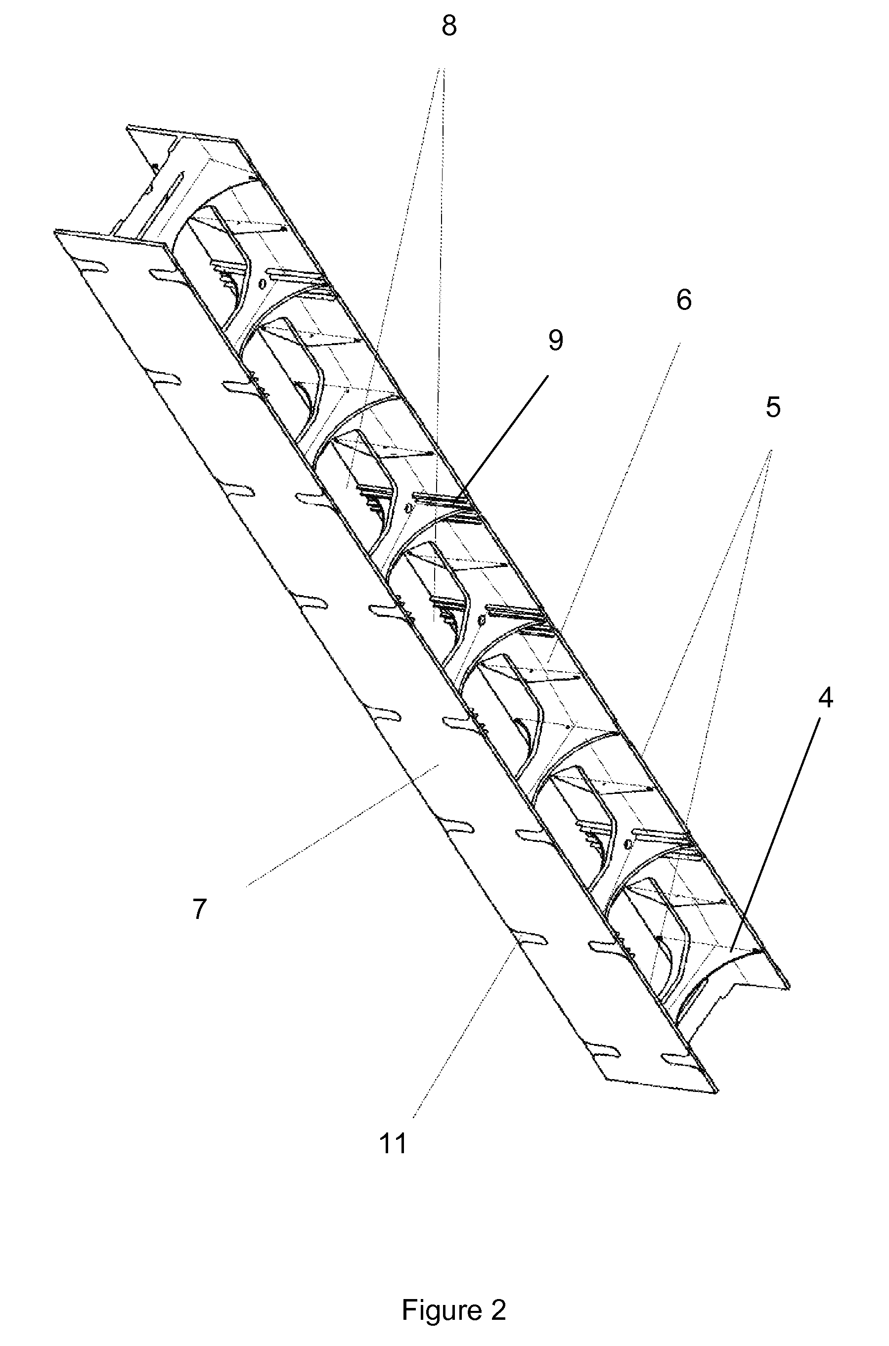
[0032]FIGS. 1 and 2 show a wall stud according to a preferred embodiment of the present invention. The wall stud 1 is used for positioning between an opposing pair of formwork boards to ensure the resulting wall is of a uniform thickness and to keep the formwork boards in place while material is being placed between the formwork boards. The wall stud 1 includes a body 3 and two side walls 5 located on opposing sides of the body. Each side wall 5 has an inner face 6 and outer face 7. The wall stud also may have two joiner sections 10. The stud body 3 has at least one opening 8 adapted to receive at least one reinforcing rod. The outer face 7 of the side walls 5 is securable to the formwork board. The joiner sections 10 are adapted to receive a stud joiner clip 22 (shown in FIGS. 6 to 7) for securing...


PUM


Abstract

A wall stud for positioning between an opposing pair of formwork boards. The wall stud including a body and two side walls located on opposing sides of the body. Each side wall having an inner face and an outer face, wherein: the body has at least one opening adapted to receive at least one reinforcing rod. The outer face of the side walls are securable to a formwork board, and the body is affixed to approximately the center of the inner face of each side wall so that a horizontal cross-section of the stud is substantially an H shape.

Description

PRIORITY CLAIM[0001]The present application is a National Phase entry of PCT Application No. PCT / AU2012 / 000706, filed Jun. 20, 2012, which claims priority to Australian Application No. 201190404, filed Jun. 20, 2011, said applications being hereby incorporated by reference herein in their entirety.FIELD OF THE INVENTION[0002]This invention relates in general to concrete wall production, and more particularly to a wall stud, and wall construction system, preferably made from plastic.BACKGROUND TO THE INVENTION[0003]To erect a vertical concrete wall, pre-cast tilt-up concrete panels are commonly used. Another commonly used technique is to use formwork in-situ to support the concrete and reinforcing bars until the concrete has set and cured, after which the formwork is removed.[0004]An alternative way of constructing walls is to manufacture hollow panels which can be manufactured off site, delivered to the building site, erected and filled with concrete on site. These hollow panels con...

Claims


Application Information

Patent Timeline
Patent Type & Authority Patents(United States)
IPC IPC(8): E04C3/00E04B2/86E04C3/28E04C5/16E04B2/54E04C3/04
CPCE04C3/28E04B2/54E04B2/8611E04B2/8635E04C5/168E04C2003/0452
Inventor FIELDER, WERNER
Owner SAFARI HEIGHTS
Why Eureka
Try Eureka