
Controlling data center cooling

a data center and cooling technology, applied in cooling/ventilation/heating modifications, lighting and heating apparatus, instruments, etc., can solve the problems of increasing the energy consumption of large data centers, increasing the cost of removing all of the heat, and increasing the cost of cooling, so as to reduce the amount of energy needed and improve performance.

Active Publication Date: 2015-07-28
GOOGLE LLC
View PDF29 Cites 23 Cited by
  • Summary
  • Abstract
  • Description
  • Claims
  • Application Information

AI Technical Summary

Benefits of technology

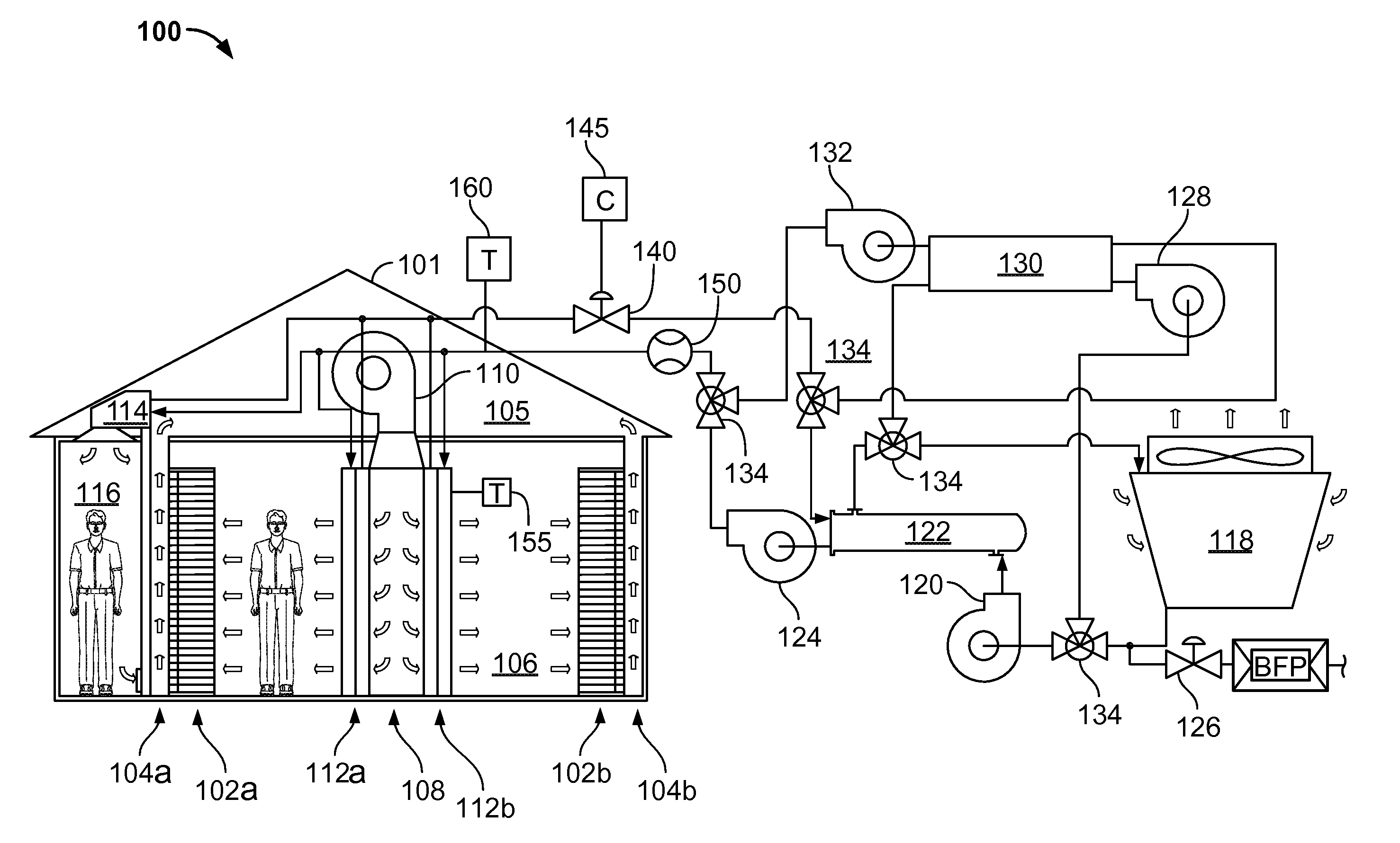
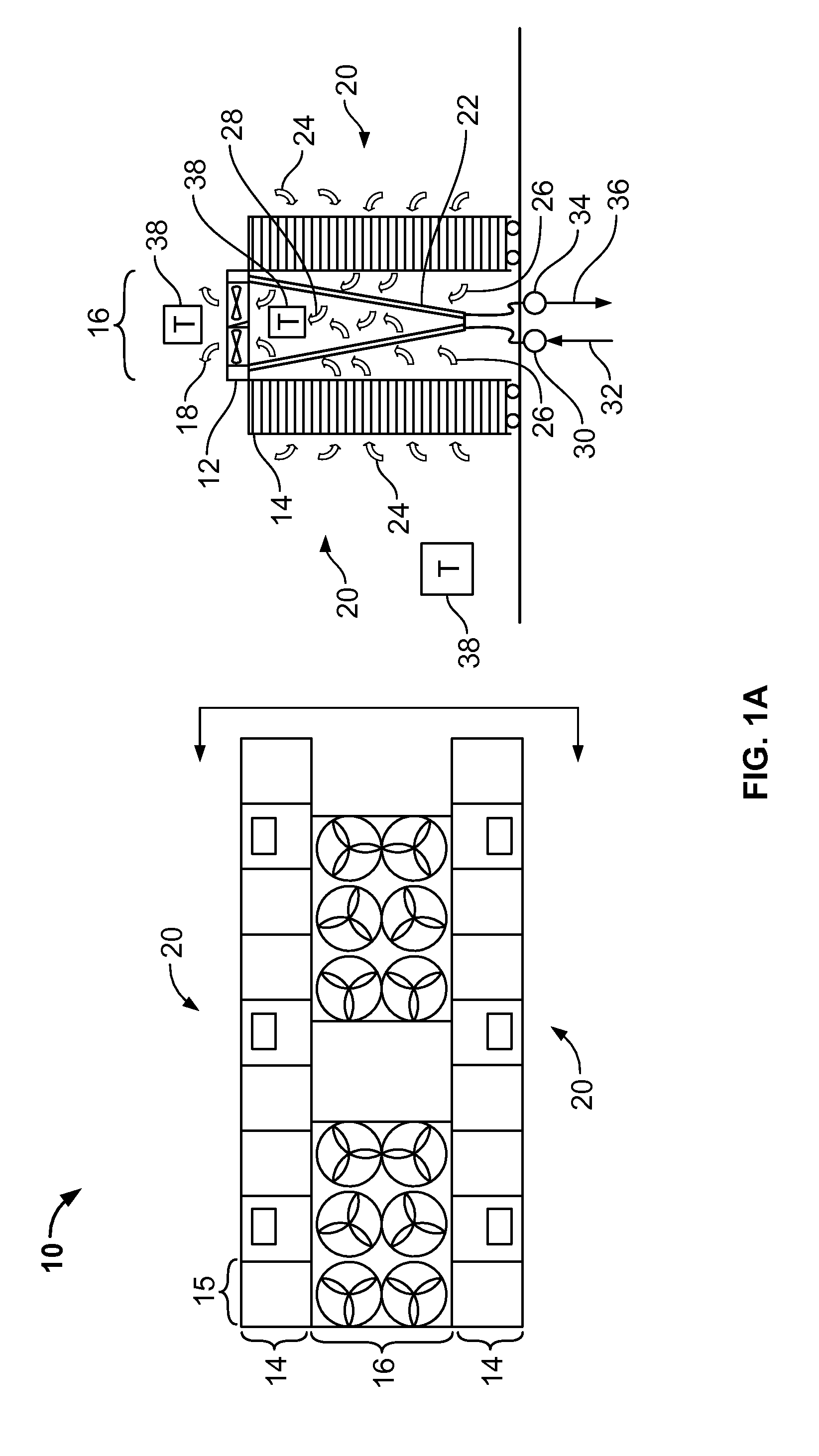
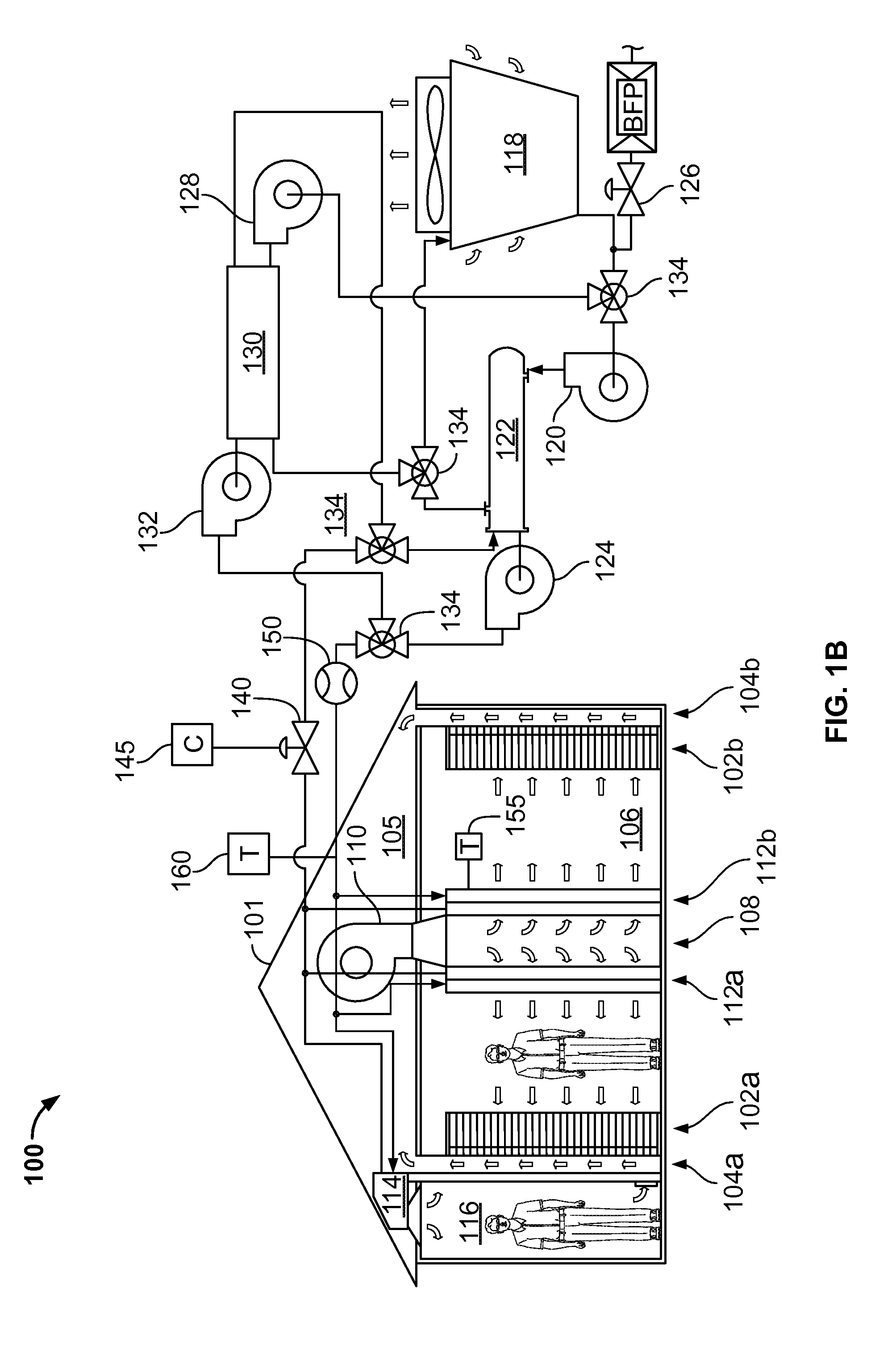
[0053]Various embodiments of systems and methods for providing cooling for areas containing electronic equipment may include one or more of the following advantages. For example, a cooling apparatus operable to cool a data center may implement a static approach control scheme to apply a single, fixed value for an approach temperature set point to all (or most) cooling apparatus in the data center. The cooling apparatus may be controlled to maintain the approach temperature set point (i.e., a difference in temperature between airflow leaving the apparatus and fluid entering the apparatus) rather than, for instance, simply a leaving air temperature from the apparatus. The cooling apparatus may allocate cooling fluid (e.g., from a central plant or other cooling facility) to follow a data center cooling load based solely on information available locally at each cooling apparatus. The cooling apparatus can thus be controlled so that a temperature in the data center may follow the seasons in accordance with weather impact on cooling plant capacity (e.g., by maximizing free cooling opportunities). In addition, embodiments of systems and methods for providing cooling for areas containing electronic equipment may provide for a dynamic approach temperature control (e.g., approach temperature set point for one or more cooling apparatus may vary over time). For example, multiple cooling apparatuses may be controlled based on one or more approach temperature set points in order to, for instance, track a cooling load in the data center that varies spatially and temporally. In some embodiments, an available capacity of cooling fluid from a central cooling plant can be more optimally deployed.
[0054]Further, the cooling load may be handled by the cooling apparatus in response to such factors as, for example, the types of electronic devices deployed at various locations on the data center floor; the types of services executed by such devices; an actual aggregate heat load on the data center floor; and an actual cooling system capacity under current weather conditions. Further, by dynamically varying the approach temperature, oversubscription (e.g., design of a cooling system with more cooling fluid available than used) of a cooling fluid supply may be diminished. As another example, utilizing a master controller to dynamically vary the approach temperature may allow for using more cooling fluid only when the chillers won't be engaged in order to reduce central cooling plant operational expenses.

Problems solved by technology

Many forget that this speed often comes with a cost-higher power consumption.
Thus, the cost of removing all of the heat can also be a major cost of operating large data centers.
That cost typically involves the use of even more energy, in the form of electricity and natural gas, to operate chillers, condensers, pumps, fans, cooling towers, and other related components.
Heat removal can also be important because, although microprocessors may not be as sensitive to heat as are people, increases in temperature can cause great increases in microprocessor errors and failures.
In sum, a data center requires a large amount of electricity to power the critical load, and even more electricity to cool the load.
Further, by dynamically varying the approach temperature, oversubscription (e.g., design of a cooling system with more cooling fluid available than used) of a cooling fluid supply may be diminished.

Method used


Image

  • Controlling data center cooling
  • Controlling data center cooling
  • Controlling data center cooling

Examples


Embodiment Construction

[0065]This disclosure relates to systems and methods for providing cooling for areas that contain electronic equipment, such as computer server rooms and server racks in computer data centers. For example, in some example embodiments, a cooling apparatus may be controlled to maintain a static or dynamic approach temperature that is defined by a difference between a leaving air temperature of the cooling apparatus and an entering cooling fluid temperature of the cooling apparatus. For example, in some embodiments, a data center cooling system may include multiple cooling units that are arranged to provide cool air to rack-mounted electronic equipment. One or more control valves can be in fluid communication with the cooling units to circulate the cooling fluid to the cooling units. One or more controllers (which may be centrally located or distributed) can in turn be communicably coupled to the control valves to modulate the valves to maintain the approach temperature set point. In s...


PUM


Abstract

A data center cooling system includes a data center having electronic equipment that is supported in multiple racks; a cooling fluid source; multiple cooling units in the data center, where each cooling unit is configured to cool air warmed by a sub-set of the electronic equipment in the data center; multiple control valves, including a control valve associated with a particular cooling unit of the cooling units; and a controller arranged to modulate the control valve associated with a particular cooling unit, to open or close the control valve to substantially maintain an approach temperature set point of the particular cooling unit.

Description

CLAIM OF PRIORITY[0001]This application claims priority to U.S. Provisional Patent Application Ser. No. 61 / 608,290, filed on Mar. 8, 2012, the entire contents of which are hereby incorporated by reference.TECHNICAL BACKGROUND[0002]This disclosure relates to systems and methods for providing cooling for areas that contain electronic equipment, such as computer server rooms and server racks in computer data centers.BACKGROUND[0003]Computer users often focus on the speed of computer microprocessors (e.g., megahertz and gigahertz). Many forget that this speed often comes with a cost-higher power consumption. For one or two home PCs, this extra power may be negligible when compared to the cost of running the many other electrical appliances in a home. But in data center applications, where thousands of microprocessors may be operated, electrical power requirements can be very important.[0004]Power consumption is also, in effect, a double whammy. Not only must a data center operator pay f...

Claims


Application Information

Patent Timeline
Patent Type & Authority Patents(United States)
IPC IPC(8): H05K7/20F28F27/02
CPCF28F27/02H05K7/20745H05K7/20836
Inventor IMWALLE, GREGORY P.KOWALSKI, THOMAS R.CARLSON, ANDREW B.
Owner GOOGLE LLC
Learn More