
Magnetic position detection apparatus

a magnetic position and detection apparatus technology, applied in the direction of electrical/magnetically converting sensor output, galvano-magnetic devices, instruments, etc., can solve the problems of increasing manufacturing costs and difficult manufacturing, and achieve the effect of reducing the variance of a signal, facilitating manufacturing, and inexpensive magnetic position detection

Active Publication Date: 2015-07-28
MITSUBISHI ELECTRIC CORP
View PDF19 Cites 5 Cited by
  • Summary
  • Abstract
  • Description
  • Claims
  • Application Information

AI Technical Summary

Benefits of technology

[0013]The invention therefore has an object to provide an inexpensive magnetic position detection apparatus by reducing a variance of a signal and thereby facilitating the manufacturing and further to improve characteristics of the magnetic position detection apparatus.
[0015]According to the configuration above, when the magnetic position detection apparatus is present solely and not opposed to the magnetic mobile object, owing to the locations of the first and second magneto-electric converting elements, electric resistance values of the bridge circuit formed of the first and second magneto-electric converting elements are in balance. It thus becomes possible to suppress a variance of an output signal of the magnetic position detection apparatus in response to a manufacturing variance, such as a variance of magnetic characteristics of the magneto-electric converting elements and a variance of combining positions of the magneto-electric converting elements and the magnet in comparison with the related art. The magnetic position detection apparatus can be therefore manufactured more readily at a lower cost. Further, it becomes possible to improve a characteristic relating to sensitivities of the magneto-electric converting elements, such as, in particular, a temperature characteristic of a differential output of the bridge circuit.

Problems solved by technology

However, either countermeasure makes the manufacturing difficult and further increases the manufacturing costs.

Method used


Image

  • Magnetic position detection apparatus
  • Magnetic position detection apparatus
  • Magnetic position detection apparatus

Examples


first embodiment

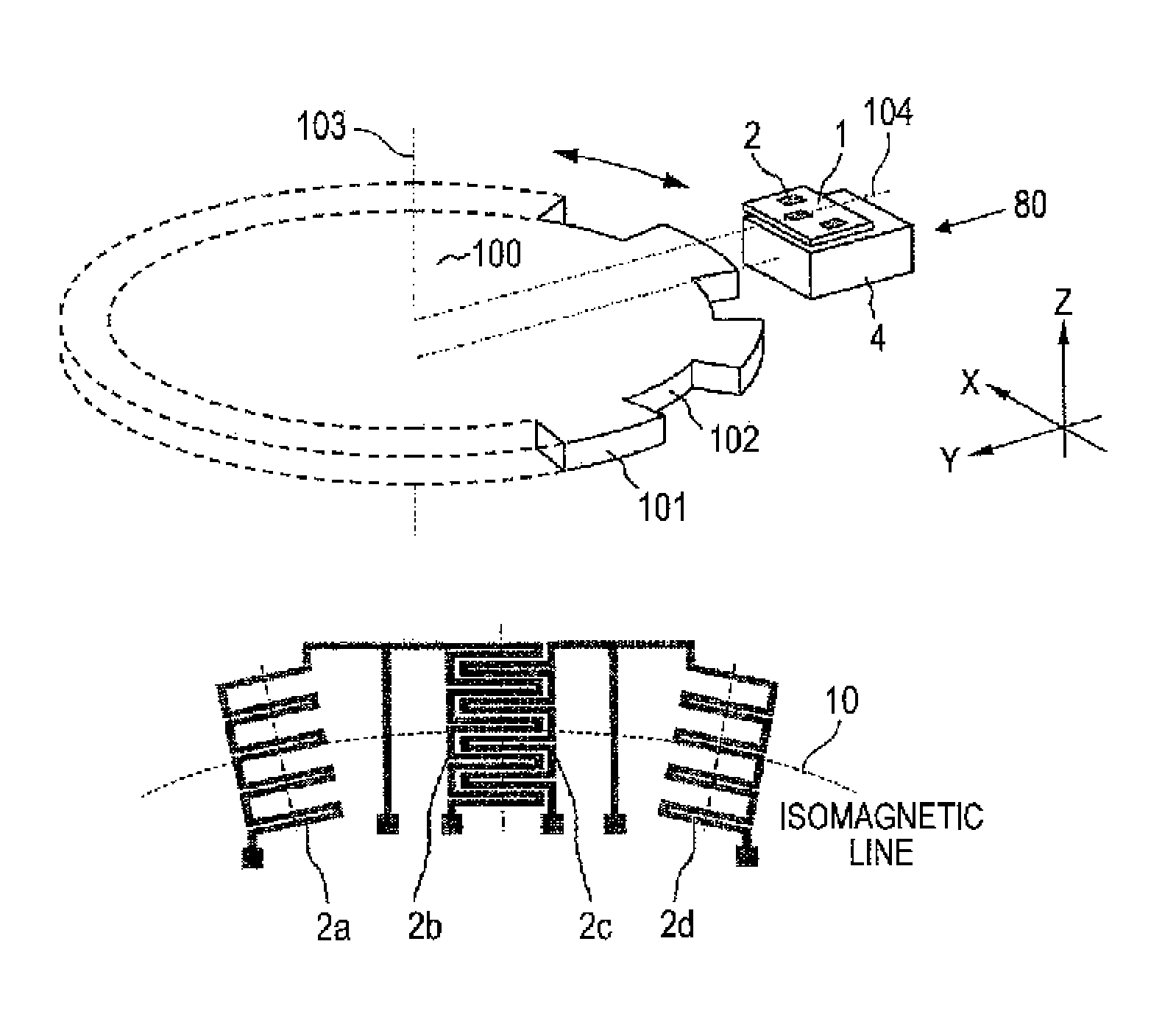
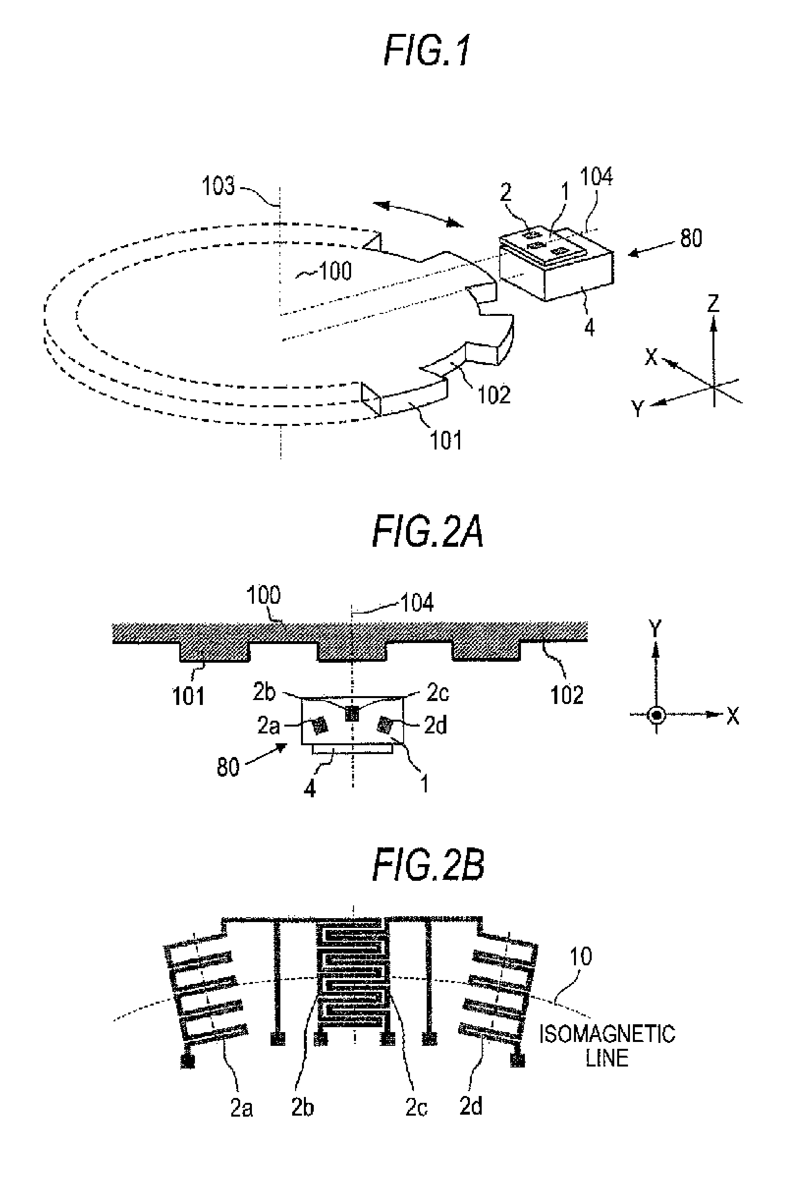
[0038]FIG. 1 shows an example where a magnetic position detection apparatus 80 according to a first embodiment of the invention is disposed relative to a magnetic mobile object 100.

[0039]The magnetic mobile object 100 is a substantially disc-shaped magnetic object rotating about a rotation axis (center axis) 103. A radially-protruding tooth portion 101 and a radially-recessed slot portion 102 are formed alternately all along the circumference of the magnetic mobile object 100.

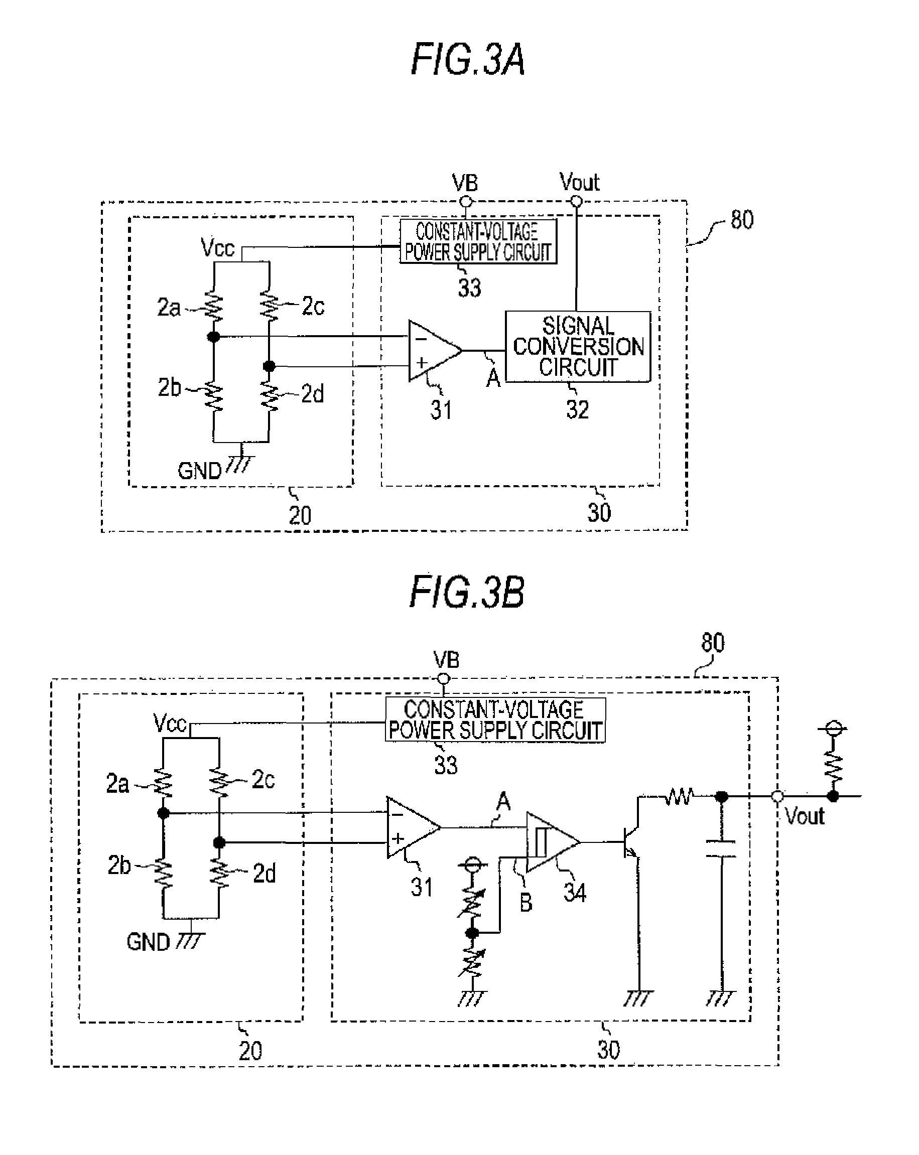
[0040]In order to detect a movement of the magnetic mobile object 100, the magnetic position detection apparatus 80 is disposed with a predetermined spacing from the magnetic mobile object 100. The magnetic position detection apparatus 80 includes a substrate 1, a bridge circuit 20 including a magneto-electric converting element 2 (see FIGS. 3A and 3B), a detection circuit 30 (see FIGS. 3A and 3B), and a magnet 4. The bridge circuit 20 has first through fourth magneto-electric converting elements 2a through 2d ...

second embodiment

[0055]A magnetic position detection apparatus 80 according to a second embodiment of the invention is an improved example of the first embodiment above and additionally includes a flux guide between a magneto-electric converting element 2 and a magnet 4.

[0056]FIGS. 8A through 8C are plan views and a side view of the magnetic position detection apparatus 80 according to the second embodiment of the invention. FIG. 8A is a plan view showing locations of a substrate 1, a magnet 4, and a flux guide 5. FIG. 8b is a plan view showing, in enlargement, locations of first through fourth magneto-electric converting elements 2a through 2d by way of example. FIG. 8C is a side view showing locations of the substrate 1, the magnet4, and the flux guide 5 by way of example.

[0057]Referring to FIGS. 8A and 8B, a surface of the substrate 1 is substantially perpendicular to a magnetization direction of the magnet 4 and the flux guide 5 has a surface perpendicular to the magnetization direction of the m...

third embodiment

[0065]A magnetic position detection apparatus 80 according to a third embodiment of the invention includes, as with the second embodiment above, a flux guide 5 made of a magnetic material between a magneto-electric converting element 2 and a magnet 4. The flux guide 5 is, however, of a shape different from the shape of the counterpart in the second embodiment above and it is an improved example of the counterpart in the second embodiment above.

[0066]FIG. 11 is a perspective view of the magnetic position detection apparatus 80 according to the third embodiment of the invention showing a location thereof relative to a magnetic mobile object 100 by way of example.

[0067]FIG. 12 is a side view showing locations a substrate 1, a magnet 4, and a flux guide 5 of the magnetic position detection apparatus 80 according to the third embodiment of the invention by way of example.

[0068]As are shown in FIG. 11 and FIG. 12, a surface of the substrate 1 is substantially perpendicular to a magnetizat...


PUM


Abstract

A magnetic position detection apparatus includes a substrate, a magnet, a bridge circuit including first through fourth magneto-electric converting elements formed on the substrate, and a detection circuit. A substrate surface is substantially perpendicular to a magnet magnetization direction. The second and third magneto-electric converting elements are, when viewed along the magnet magnetization direction, disposed to be on or in the vicinity of a straight line passing through a center point of a magnetic pole of the magnet and parallel to a straight line perpendicular to both the magnet magnetization direction and the magnetic mobile object. The first and fourth magneto-electric converting elements are disposed so that, when not opposed to the magnetic mobile object, a component of a substrate of a magnetic field to be applied thereto is substantially same as that of a magnetic field to be applied to the second and third magneto-electric converting elements.

Description

BACKGROUND OF THE INVENTION[0001]1. Field of the Invention[0002]The present invention relates to a magnetic position detection apparatus that magnetically detects a movement of a magnetic mobile object.[0003]2. Background Art[0004]There is a detection apparatus formed of a magneto-electric converting element and a magnet to magnetically detect a movement of a magnetic mobile object. The magneto-electric converting element referred to herein means an element whose electric resistance value varies with a magnetic field applied thereto, such as an MR (Magneto-Resistance) element. Because a magnetic field to be applied to the magneto-electric converting element by the magnet varies in association with a movement of the magnetic mobile object opposed to the magnet, the movement of the magnetic mobile object can be detected as a variance of the electric resistance value.[0005]For example, a magnetic position detection apparatus disclosed in Japanese Patent No. 3682052 (Patent Document 1) ...

Claims


Application Information

Patent Timeline
Patent Type & Authority Patents(United States)
IPC IPC(8): G01R33/09G01B7/30G01D5/14G01B7/14G01D5/245
CPCG01D5/147G01D5/2451G01D2205/40
Inventor KAWANO, YUJIKOBAYASHI, HIROSHINISHIKAWA, KAZUYASUFURUKAWA, TAISUKE
Owner MITSUBISHI ELECTRIC CORP
Learn More