
Catheter assembly

a catheter and assembly technology, applied in the field of catheter assembly, can solve the problems of reducing the penetration rate, difficult to insert the plug, and difficult to simultaneously satisfy the hemostasis and penetrability of the valve mechanism of the catheter assembly, and achieve the effect of improving the hemostasis and penetrability of the valve mechanism configured with the valve body and the insertion member, and simple configuration

Active Publication Date: 2015-08-04
TERUMO KK
View PDF6 Cites 25 Cited by
  • Summary
  • Abstract
  • Description
  • Claims
  • Application Information

AI Technical Summary

Benefits of technology

The present invention relates to a hemostasis valve used in catheter assemblies. The valve has an opening / closing part formed in a single slit shape that can be closed to prevent blood from flowing out when not in use. The insertion member can easily enter into the opening / closing part, improving both blood hemostasis and penetrability. The shape of the opening / closing part is also improved to ensure smooth advancement of the insertion member. A sealing member is included to prevent fluid from flowing out and to exhaust air existing from the flow passage. The valve mechanism is simple in configuration and can improve the efficiency of connecting operation of the transfusion tube.

Problems solved by technology

However, in the valve mechanism configured with the hemostasis valve and the plug, when hemostasis is to be improved, the slit of the hemostasis valve is configured not to open easily, which reduces penetrability and makes it difficult to insert the plug.
That is, it is difficult to simultaneously satisfy both hemostasis and penetrability of the valve mechanism of the catheter assembly.

Method used


Image

  • Catheter assembly
  • Catheter assembly
  • Catheter assembly

Examples


example

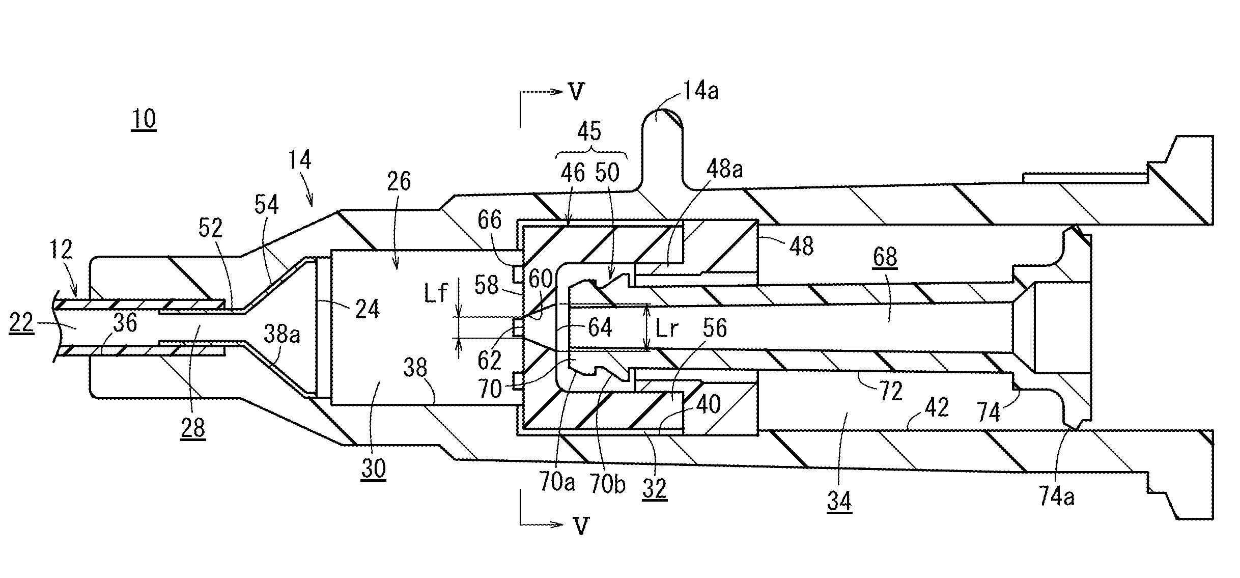
[0090]Comparison is made regarding penetrability and hemostasis for the hemostasis valve 46 including the slit 60 according to an embodiment of the present invention and a hemostasis valve including a silt having another shape. Note that a catheter assembly 10 having the same components, except the hemostasis valve, is used in the comparison.

[0091]FIG. 8 is a table in which penetrability and hemostasis for a slit 60 of the hemostasis valve 46 according to one embodiment (example) and for a slit of a hemostasis valve of comparative examples 1 to 4 are shown.

[0092]As illustrated in FIG. 8, for the hemostasis valve 46 of the inventive example, the linear length Lf at the distal end opening 62 is provided to be 0.3 mm, and the linear length Lr at the proximal end opening 64 is provided to be 0.4 mm. For the hemostasis valve of the comparative example 1, the linear length Lf at the distal end opening and the linear length Lr at the proximal end opening are provided to be the same value o...


PUM


Abstract

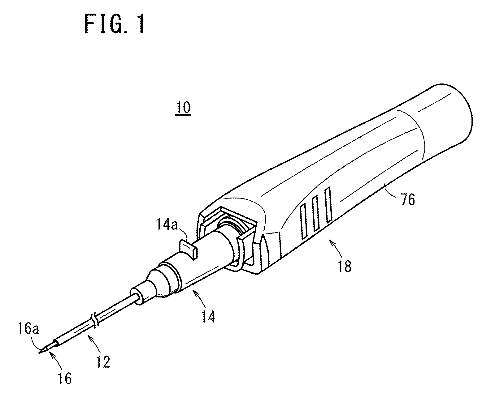
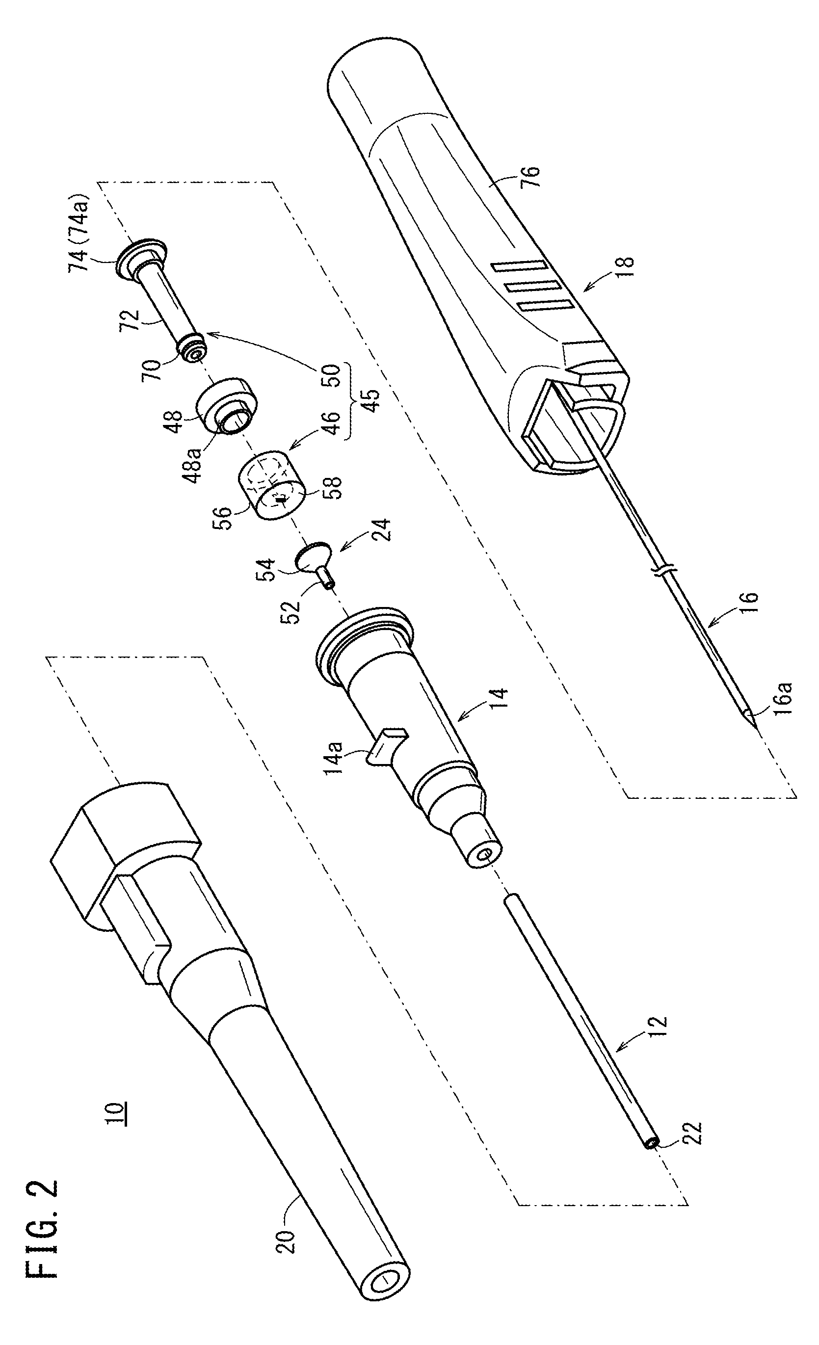
A catheter assembly includes a tubular insertion portion; a support portion that is connected to a proximal end side of the insertion portion and has therein a flow passage communicating with an inside of the insertion portion; a valve body that is disposed in the flow passage and includes: a blocking membrane configured to inhibit a flow of fluid, and an opening / closing part configured such that the blocking membrane is at least partially openable and closeable via the opening / closing part; and an insertion member which is arranged proximal of the blocking membrane and is insertable into the opening / closing part by moving in a distal direction. The opening / closing part is formed as a single slit penetrating the blocking membrane, the slit having a distal end opening and a proximal end opening, and a length of the distal end opening being smaller than a length of the proximal end opening.

Description

CROSS-REFERENCE TO RELATED APPLICATIONS[0001]This application is a continuation application filed under 35 U.S.C. 111(a) claiming the benefit under 35 U.S.C. §§120 and 365(c) of PCT International Application No. PCT / JP2012 / 073328 filed on Sep. 12, 2012, which is based upon and claims the benefit of priority of Japanese Application No. 2011-212694 filed on Sep. 28, 2011, the entire contents of which are hereby incorporated by reference in their entireties.BACKGROUND[0002]1. Technical Field[0003]The present disclosure relates to a catheter assembly which dwells in a blood vessel or on a skin of a patient, allowing transfusion to the patient.[0004]2. Background Art[0005]Generally, when transfusion is carried out to a patient, an indwelling needle is pierced (inserted) in a blood vessel of a patient so as to dwell in the blood vessel. The distal end portion of a transfusion tube and the proximal end portion of the indwelling needle exposed on the skin are connected to provide communicat...

Claims


Application Information

Patent Timeline
Patent Type & Authority Patents(United States)
IPC IPC(8): A61M5/178A61M25/06A61M25/00A61M39/06
CPCA61M25/0606A61M25/0075A61M25/0084A61M2039/064A61M2039/0653
Inventor NISHIMURA, YUKATANABE, HIDENORIUEDA, YASUHIRO
Owner TERUMO KK
Learn More