Solid axle steering and suspension systems

a technology of steering and suspension system and solid axle, which is applied in the direction of steering linkage, pivoted suspension arms, transportation and packaging, etc., can solve the problems of poor steering precision, deficiency of suspension and steering system, and uncomfortable ride of vehicles, so as to reduce the amount of bumps throughout suspension travel and ensure the effect of steering precision

Inactive Publication Date: 2015-08-04
BANDY RONALD SCOTT
View PDF28 Cites 9 Cited by
  • Summary
  • Abstract
  • Description
  • Claims
  • Application Information

AI Technical Summary

Benefits of technology

[0012]By controlling suspension travel particularly compression, the angular displacement of the other end of the second draglink is irrelevant the effect of which, in combination with the isolated bellcrank and the endpoints of the first draglink being coincident with those of the front passenger lower link, all cooperate to minimize bumpsteer throughout suspension travel.
[0013]In a third particular arrangement, a rack and pinion steering system replaces the steering box steering system. Known in the art for use on vehicles equipped with beam or solid front axles, the rack and pinion steering box is highly respected for steering precision and is commonly used to replace the recirculating ball steering box in vehicle steering systems. Mounted to the front axle, a slow-ratio rack and pinion steering box that is connected directly to a quick-ratio chain and sprocket assembly with a telescoping steering shaft will operate with minimal bumpsteer throughout suspension travel and articulation.
[0014]The system of suspension linkages includes two pairs of control links, the links collectively acting to locate the axle in all axes throughout suspension travel. The link configuration represents a pair of upper links and a pair of lower links each pair occupying opposing sides of the axle, whereby the angulation of the upper links keeps the axle centered beneath the vehicle throughout suspension travel thereby controlling the axle's side-to-side motion and eliminating the need for a lateral stabilizing device. The configuration is described herein with the pair of upper links being positioned between the end of the frame and axle and being angled inward from the end of the frame to the axle; and the lower links being positioned between the transmission cross-member and axle and being angled outward from the transmission cross-member to the axle. The axle ends of the upper links converge at and are attached to the top of the truss or rear differential housing, the truss or rear differential housing is located at the center of the front or rear axle, respectively. The positioning of the upper links between the end of the frame and axle opens up ample free space in the engine bay to accommodate powertrain and related components such as the engine, radiator, exhaust, accessory drive pulleys, belts, and hoses, and electrical units; thereby making the present invention a suitable triangulated 4-link front suspension system for production based vehicles.

Problems solved by technology

The Panhard bar can lead to deficiencies in suspension and steering systems, particularly when the Panhard bar is oriented alongside the draglink.
Second, when the endpoints on the Panhard bar fail to coincide with the endpoints on the draglink, the Panhard bar and draglink move through different arcs.
Bumpsteer and bump-induced yaw both contribute to an uncomfortable ride and make a vehicle handle poorly.
However, part of this neglect is likely due to packaging constraints.
Much of the area forward of the firewall is occupied by the engine and its attendant cooling, electrical, and control systems, thereby leaving little free space to accommodate the angled control links in a triangulated 4-link suspension system.

Method used


Image

  • Solid axle steering and suspension systems
  • Solid axle steering and suspension systems
  • Solid axle steering and suspension systems

Examples


Embodiment Construction

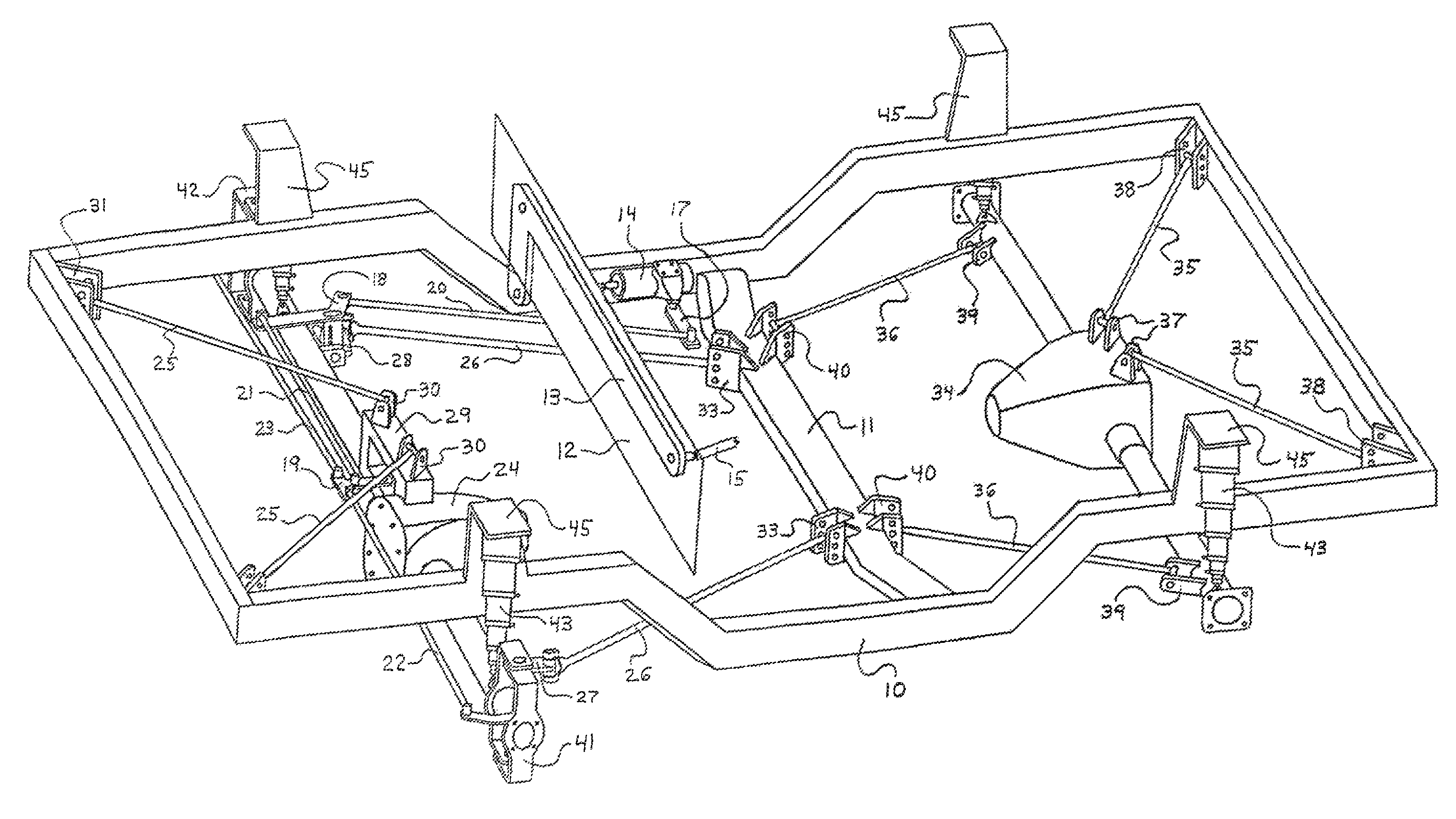
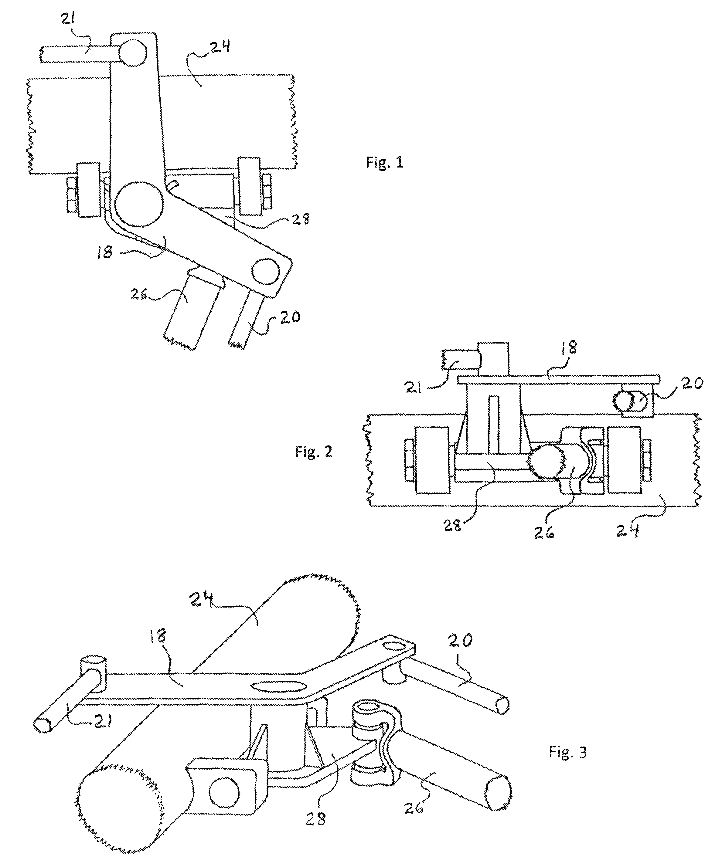
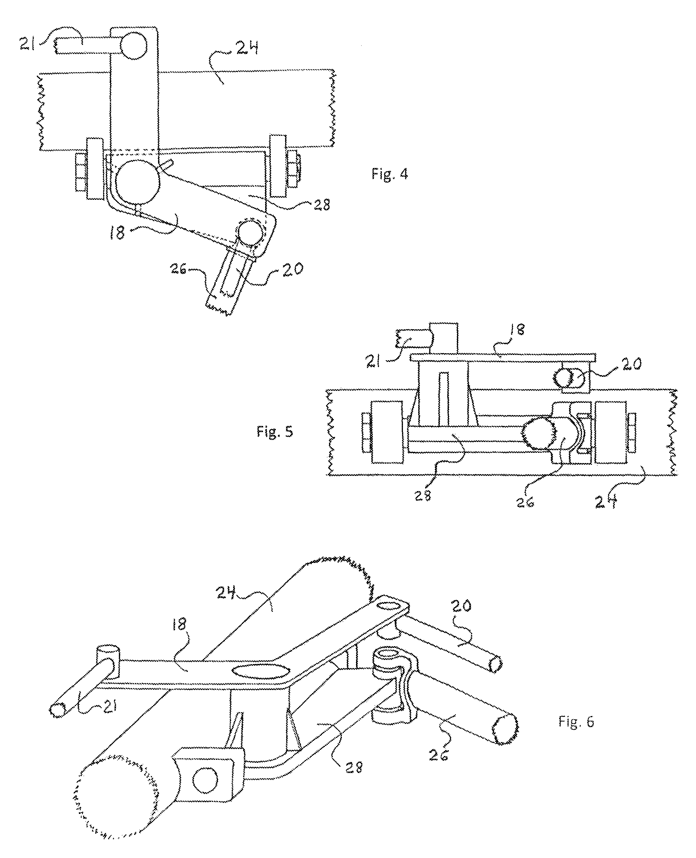
[0105]The present invention represents steering and suspension systems designed to function with a vehicle whose frame is suspended above solid or beam type axles, the front axle being steerable. Springing and damping means are supplied by the segmented air shock absorber, a shock absorber disclosed in U.S. patent application Ser. No. 13 / 854,055.

[0106]For reference: One, the longitudinal axis refers to a line passing through the center of the frame from front to back. Two, an axle exhibits lateral rotation. Lateral rotation is an artifact of the configuration of the suspension links, this configuration being one in which each pair of links is disposed on opposite sides of an axle and acts to rotate the axle about a line parallel to the lateral axis throughout suspension travel, the lateral axis passing through the center of the frame from one side to the other side. Lateral rotation, which causes a change in pinion / caster angle, can be managed by controlling the range of suspension ...


PUM


Abstract

Disclosed herein is a system of steering and suspension linkages for a beam-type solid axle arrangement, the steering system designed to operate in conjunction with the suspension system without bumpsteer throughout suspension travel. Accurate steering throughout suspension travel is satisfied with mechanical linkages that include a unique flexible joint-mounted bellcrank. The suspension system comprises two pairs of links, each pair occupying opposite sides of a solid axle, this opposed configuration offering the axle centering capability of without the packaging constraints of a triangulated 4-link suspension system, thereby facilitating its installation on production-based front solid axle vehicles.

Description

CROSS-REFERENCE TO RELATED APPLICATIONS[0001]This application represents a vehicle steering and suspension systems whereby the spring and damping means for the suspension system are supplied by the segmented air shock absorber. This novel shock absorber is covered in U.S. patent application Ser. No. 13 / 854,055.STATEMENT REGARDING FEDERALLY SPONSORED RESEARCH OR DEVELOPMENT[0002]Not ApplicableREFERENCE TO SEQUENCE LISTING, A TABLE, OR A COMPUTER PROGRAM LISTING COMPACT DISC APPENDIX[0003]Not ApplicableBACKGROUND OF THE INVENTION[0004]The link style suspension system represents a common type of suspension system utilized on vehicles equipped with a solid or beam axle. The link style suspension system offers a compliant and well-functioning method of mounting / suspending the axle to the vehicle; and, involves several different links, including upper control links, lower control links, and usually a lateral stabilizing device such as a Panhard or track bar. The combination of these links...

Claims


Application Information

Patent Timeline
Patent Type & Authority Patents(United States)
IPC IPC(8): B62D7/00B60G21/05B62D7/18B62D7/08B62D9/00B60G9/00
CPCB60G21/05B62D7/18B62D7/08B60G9/00B62D9/00B62D1/163B60G7/02B60G9/022B60G2200/30B60G2204/143
Inventor BANDY, RONALD SCOTT
Owner BANDY RONALD SCOTT
Why Eureka
Try Eureka