
Rollable display device

a display device and roll-type technology, applied in the direction of identification means, electrical apparatus casings/cabinets/drawers, instruments, etc., can solve the problems of thin profile, light weight, flexibility of fpd,

Active Publication Date: 2015-08-04
LG DISPLAY CO LTD
View PDF25 Cites 110 Cited by
  • Summary
  • Abstract
  • Description
  • Claims
  • Application Information

AI Technical Summary

Benefits of technology

The present invention provides a display device with a flexible display panel, a roller, and a printed circuit board. The flexible display panel can be selectively wound and unwound on the roller. The printed circuit board is located inside the roller and connected to the flexible display panel through a connector. The roller has an aperture with an adhesive to fix the end of the flexible display panel to the roller. A pin is used to connect the printed circuit board to the roller. The roller can be a circular cylinder or a hollow tube. In another aspect, the invention provides an elevating mechanism to extend the flexible display panel from the case. This mechanism includes a guide rail attached to the flexible display panel, two links, and a fixing bracket. A fixing bracket has a hole into which one end of the flexible display panel is inserted. The technical effects of this patent include a flexible display panel that can be conveniently wound and unwound on a roller, and an elevating mechanism to extend the display panel from a case.

Problems solved by technology

Since the FPD uses a glass substrate resistant to the heat of a fabrication process, there exists a limit to the light weight, the thin profile and the flexibility of the FPD.

Method used


Image

  • Rollable display device
  • Rollable display device
  • Rollable display device

Examples


first embodiment

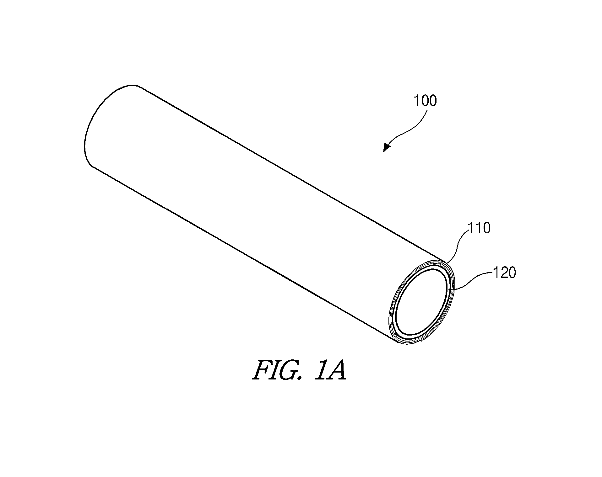
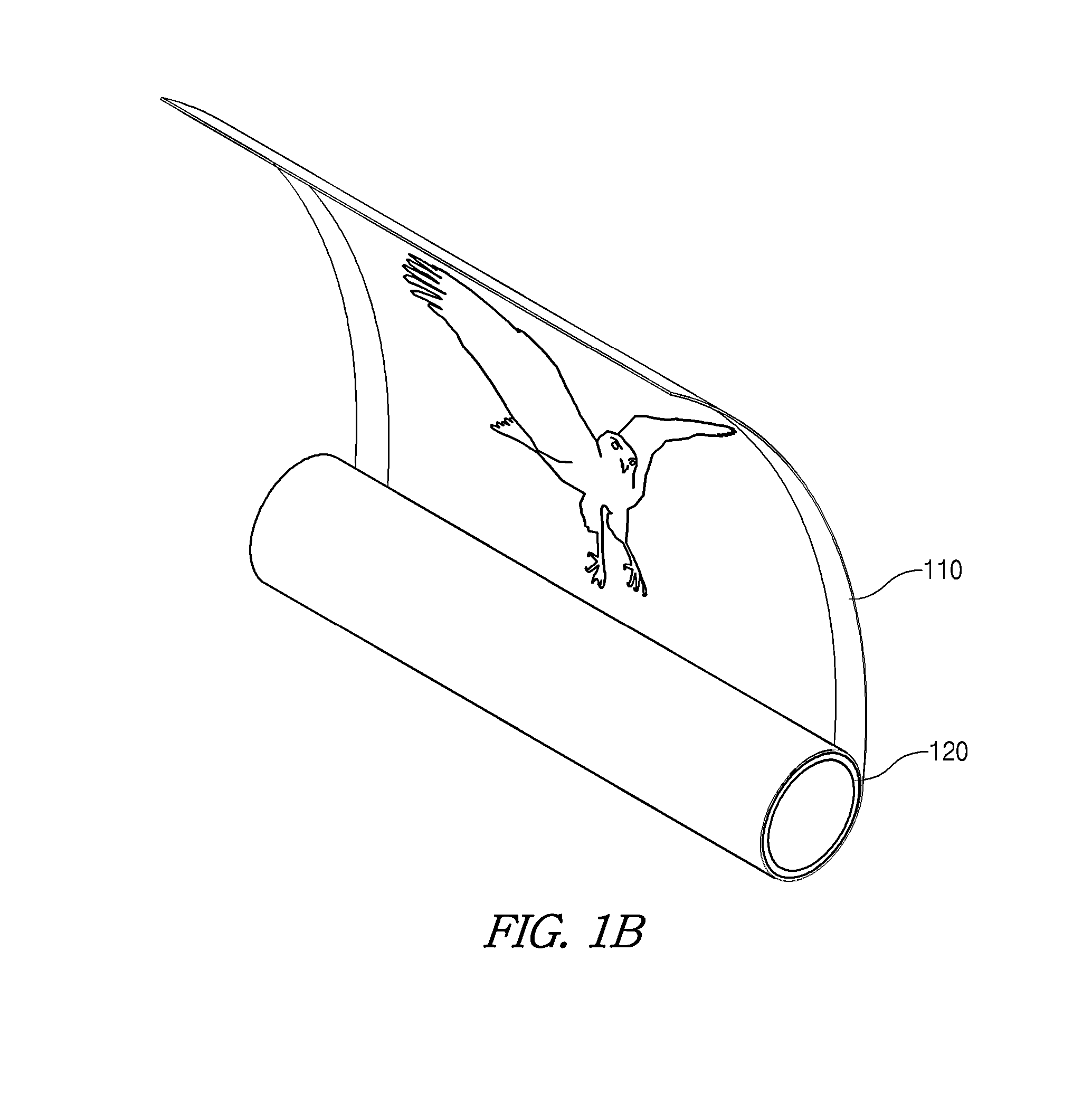
[0024]FIGS. 1A and 1B are perspective views showing a rollable display device according to the present disclosure.

[0025]In FIGS. 1A and 1B, a rollable display device 100 includes a display panel 110 for displaying an image and a roller 120 where the display panel 110 is rolled.

[0026]The display panel 110 may include one of a liquid crystal display (LCD) device, a plasma display panel (PDP) device, an organic light emitting diode (OLED) display device and a field emission display (FED) device. For example, the display panel 110 may be the OLED display device as a flexible display device which keeps displaying an image even when bent like a paper.

[0027]Since a backlight unit for the LCD device of a non-emissive type is not required for the OLED display device of an emissive type, the OLED display device has a light weight and a thin profile. In addition, the OLED display device has advantages in a viewing angle, a contrast ratio and power consumption as compared with the LCD device. F...

second embodiment

[0055]FIGS. 4A and 4B are views showing a rollable display device according to the present disclosure.

[0056]In an OFF state where a display panel does not display an image, as shown in FIG. 4A, the display panel rolled onto a roller is disposed in a case. In an ON state where the display panel displays an image, as shown in FIG. 4B, a first side of the display panel is pulled upwardly from the case and the display panel is automatically spread out. Accordingly, the rollable display device has advantages in a space application. In addition, since the rollable display device has an ultra thin profile and a light weight, the rollable display device has advantages in interior decoration and design.

[0057]In the rollable display device, the display panel is spread out upwardly, and the case may be disposed on a bottom of a user's space. Since it is not necessary to install the rollable display device on a ceiling or a sidewall, the rollable display device may create a fine view to have an...


PUM

PropertyMeasurementUnit
Adhesivityaaaaaaaaaa

Abstract

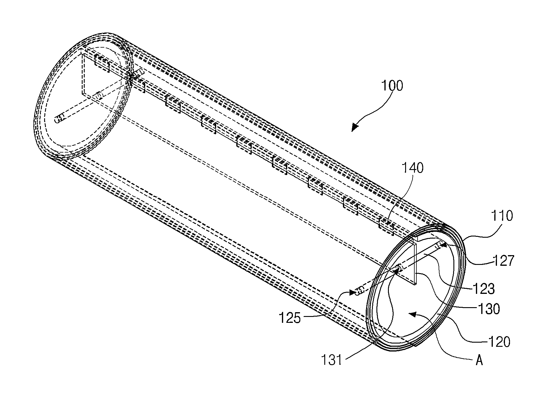
A rollable display device includes a display panel for displaying an image, a printed circuit board connected to an edge of the display panel, and a roller which the display panel is rolled onto or unrolled from. The roller has a cylindrical shape having an inner space, and the printed circuit board is disposed in the inner space.

Description

CROSS-REFERENCE TO RELATED APPLICATIONS[0001]The present application claims the benefit of priority of Korean Patent Application No. 10-2014-0092343 filed on Jul. 22, 2014, and No. 10-2014-0093790 filed on Jul. 24, 2014, which are hereby incorporated by reference for all purposes as if fully set forth herein.BACKGROUND[0002]1. Field of the Invention[0003]The present disclosure relates to a rollable display device. The present disclosure also relates to a rollable display device where a printed circuit board is stably fixed and a display panel is automatically rolled and unrolled.[0004]2. Discussion of the Related Art[0005]Recently, as the information society progresses, display devices processing and displaying a large amount of information have rapidly advanced and various flat panel displays (FPDs) have been developed. Specifically, the FPDs such as a liquid crystal display (LCD) device, a plasma display panel (PDP) device, an organic light emitting diode (OLED) display device and...

Claims


Application Information

Patent Timeline
IPC IPC(8): H05K1/00G06F1/16B65H75/44H04M1/02G09F9/30
CPCG06F1/1652B65H75/4402G09F9/301H04M1/0268B65H2301/3611B65H2301/415B65H75/28G09F15/0062H10K50/84H10K2102/311H05K1/028B65H2301/4165H05K1/147H05K5/0017H05K5/0217H05K2201/051
Inventor CHO, SEOK-HYOPARK, CHUL
Owner LG DISPLAY CO LTD
Learn More