Current-perpendicular-to-the-plane (CPP) magnetoresistive (MR) sensor structure with stacked sensors for minimization of the effect of head skew

a technology of magnetoresistive (mr) and sensor structure, which is applied in the direction of instruments, recording information storage, and disposition of heads, etc., can solve the problems of skew effect, sensor misalignment from target tracks, and limit the space between sensors

Active Publication Date: 2015-08-04
WESTERN DIGITAL TECH INC
View PDF9 Cites 34 Cited by
  • Summary
  • Abstract
  • Description
  • Claims
  • Application Information

AI Technical Summary

Benefits of technology

[0010]Embodiments of this invention relate to a TDMR multi-sensor read head that allows for the reading of adjacent tracks without the adverse effects of high head skew when the head is in the inside diameter (ID) and outside diameter (OD) regions of the disk. The read head has three stacked sensors separated by magnetic shields. The lower or first sensor is located on the bottom magnetic shield S1 and is the primary sensor that is always aligned with the target track. A second magnetic shield S2 is located on the first sensor. The middle or second sensor is located on S2 and is spaced laterally from the first sensor a distance substantially equal to the track pitch (TP). A third magnetic shield S3 is located on the second sensor and is aligned above the first sensor. The upper or third sensor is located on S3 and is aligned with the first sensor. The upper or fourth magnetic shield S4 is located on the third sensor. The spacing D between the first and third sensors in the direction orthogonal to the planes of the sensors is selected to be related to TP and a maximum skew angle (θm). The spacing D between the first and second sensors in the direction orthogonal to the planes of the sensors is preferably D / 2.

Problems solved by technology

In a TDMR sensor structure, such as a structure with two or more stacked sensors, a problem arises due to skew of the sensors at the inside diameter (ID) and outside diameter (OD) regions of the disk.
This may result in the sensors being misaligned from their target tracks.
Reducing the spacing between the stacked sensors can reduce the skew effect; however the magnetic shields must have a minimum thickness to be effective, which limits how close the sensors can be spaced.

Method used


Image

  • Current-perpendicular-to-the-plane (CPP) magnetoresistive (MR) sensor structure with stacked sensors for minimization of the effect of head skew
  • Current-perpendicular-to-the-plane (CPP) magnetoresistive (MR) sensor structure with stacked sensors for minimization of the effect of head skew
  • Current-perpendicular-to-the-plane (CPP) magnetoresistive (MR) sensor structure with stacked sensors for minimization of the effect of head skew

Examples


Embodiment Construction

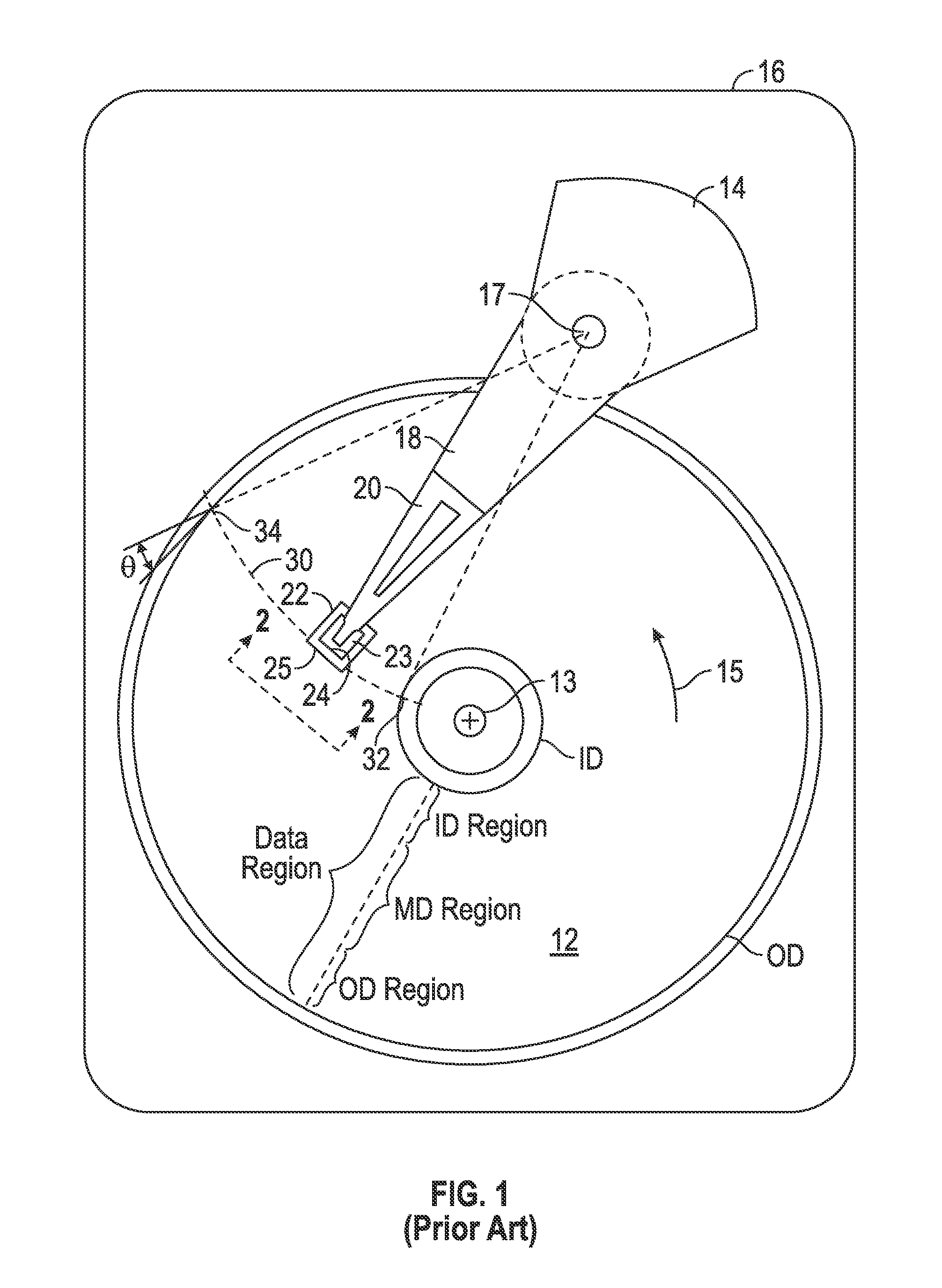
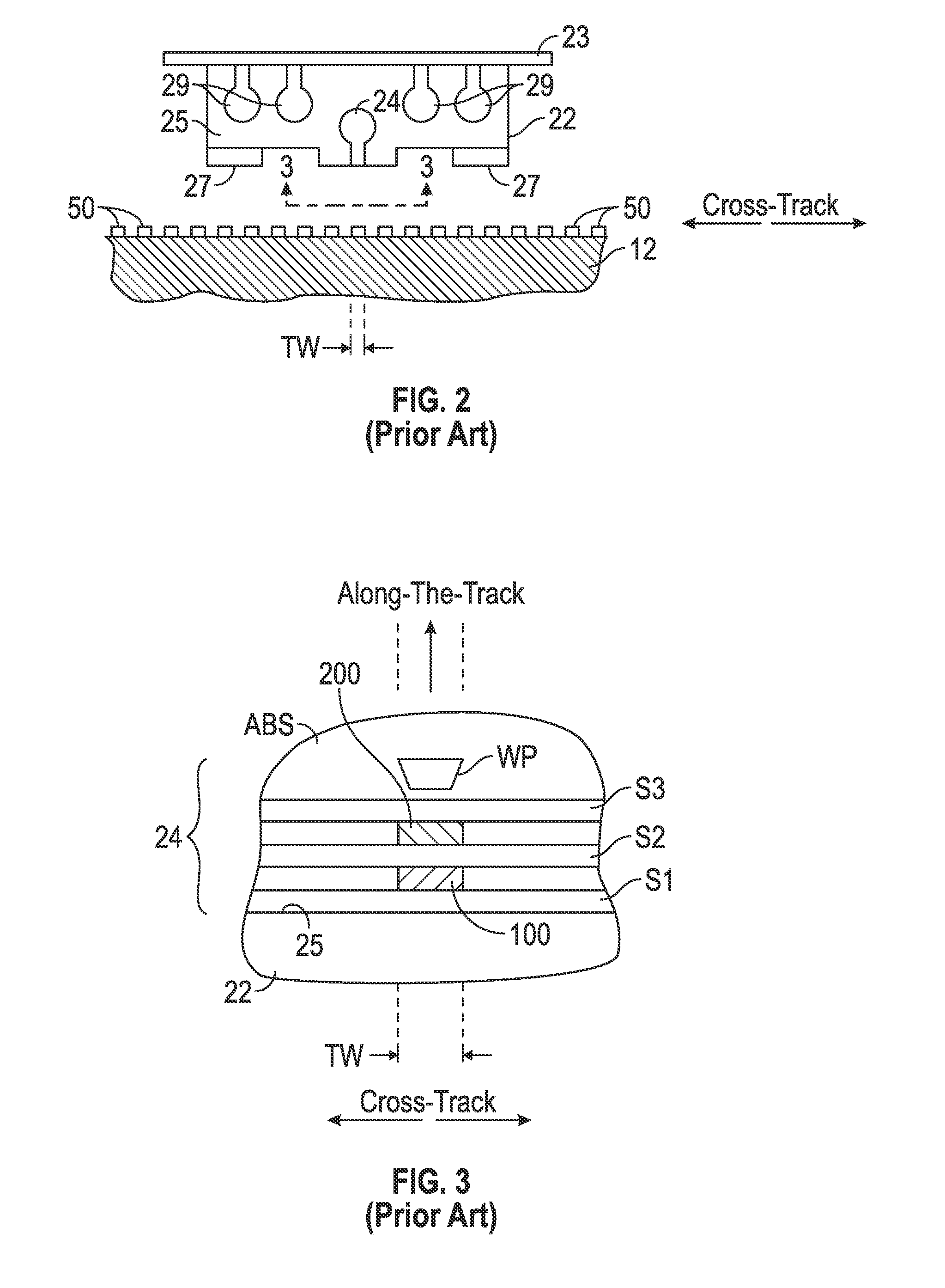
[0022]The CPP magnetoresistive (MR) sensor structure of this invention has application for use in a magnetic recording disk drive, the operation of which will be briefly described with reference to FIGS. 1-3. FIG. 1 is a block diagram of a conventional magnetic recording hard disk drive that can function for two-dimensional magnetic recording (TDMR). The disk drive includes a magnetic recording disk 12 and a rotary voice coil motor (VCM) actuator 14 supported on a disk drive housing or base 16. The disk 12 has a center of rotation 13 and is rotated in direction 15 by a spindle motor (not shown) mounted to base 16. The actuator 14 pivots about axis 17 and includes a rigid actuator arm 18. A generally flexible suspension 20 includes a flexure element 23 and is attached to the end of arm 18. A head carrier or air-bearing slider 22 is attached to the flexure 23. A magnetic recording read / write head 24 is formed on the trailing surface 25 of slider 22. The flexure 23 and suspension 20 en...


PUM

PropertyMeasurementUnit
skew angleaaaaaaaaaa
thicknessaaaaaaaaaa
thicknessaaaaaaaaaa

Abstract

A two-dimensional magnetic recording (TDMR) multi-sensor read head has three stacked sensors separated by magnetic shields. The lower sensor is the primary sensor that is always aligned with the target track. The middle sensor is spaced laterally from the lower sensor a distance substantially equal to the track pitch (TP). The upper sensor is aligned with the lower sensor. The spacing D between the lower and upper sensors is selected to be related to TP and a maximum skew angle, where the skew angle is the angle between a line orthogonal to the sensor and the data track that varies with radial position of the head. The read head is connected to circuitry that selects two of the three sensors to be the active sensors depending on the radial position of the head and thus the skew angle of the head.

Description

BACKGROUND OF THE INVENTION[0001]1. Field of the Invention[0002]The invention relates generally to a current-perpendicular-to-the-plane (CPP) magnetoresistive (MR) sensor structure for two-dimensional magnetic recording (TDMR).[0003]2. Background of the Invention[0004]One type of conventional magnetoresistive (MR) sensor used as the read head in magnetic recording disk drives is a “spin-valve” sensor based on the giant magnetoresistance (GMR) effect. A GMR spin-valve sensor has a stack of layers that includes two ferromagnetic layers separated by a nonmagnetic electrically conductive spacer layer, which is typically copper (Cu) or silver (Ag). One ferromagnetic layer adjacent to the spacer layer has its magnetization direction fixed, such as by being pinned by exchange coupling with an adjacent antiferromagnetic layer, and is referred to as the reference or pinned layer. The other ferromagnetic layer adjacent to the spacer layer has its magnetization direction free to rotate in the ...

Claims


Application Information

Patent Timeline
Patent Type & Authority Patents(United States)
IPC IPC(8): G11B5/39G11B5/115G11B5/265
CPCG11B5/3912G11B5/265G11B5/3954G11B5/3958G11B5/3974G11B5/4886G11B5/5539
Inventor HATTORI, MASASHIMEGURO, KENICHINISHIOKA, KOUICHIWAGATSUMA, TAKASHIYOSHIDA, NOBUO
Owner WESTERN DIGITAL TECH INC
Why Eureka
Try Eureka