Light-emitting device and method for manufacturing light-emitting device
a technology of light-emitting devices and light-emitting surfaces, which is applied in the direction of semiconductor devices, organic semiconductor devices, electrical devices, etc., can solve the problems of non-uniform brightness distribution of light-emitting surfaces, and achieve uniform brightness distribution, high luminous efficiency, and easy manufacturing
- Summary
- Abstract
- Description
- Claims
- Application Information
AI Technical Summary
Benefits of technology
Problems solved by technology
Method used
Image
Examples
first exemplary embodiment
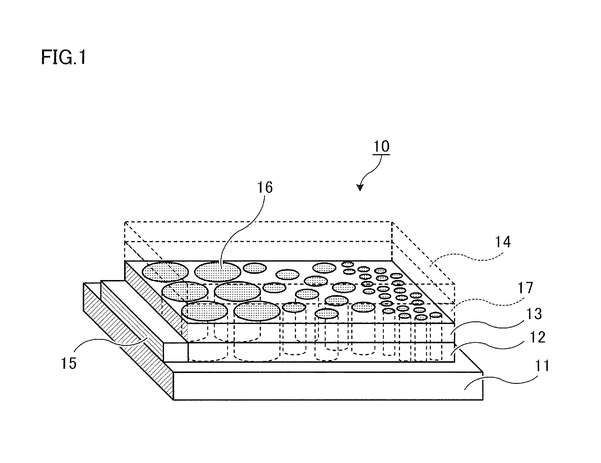
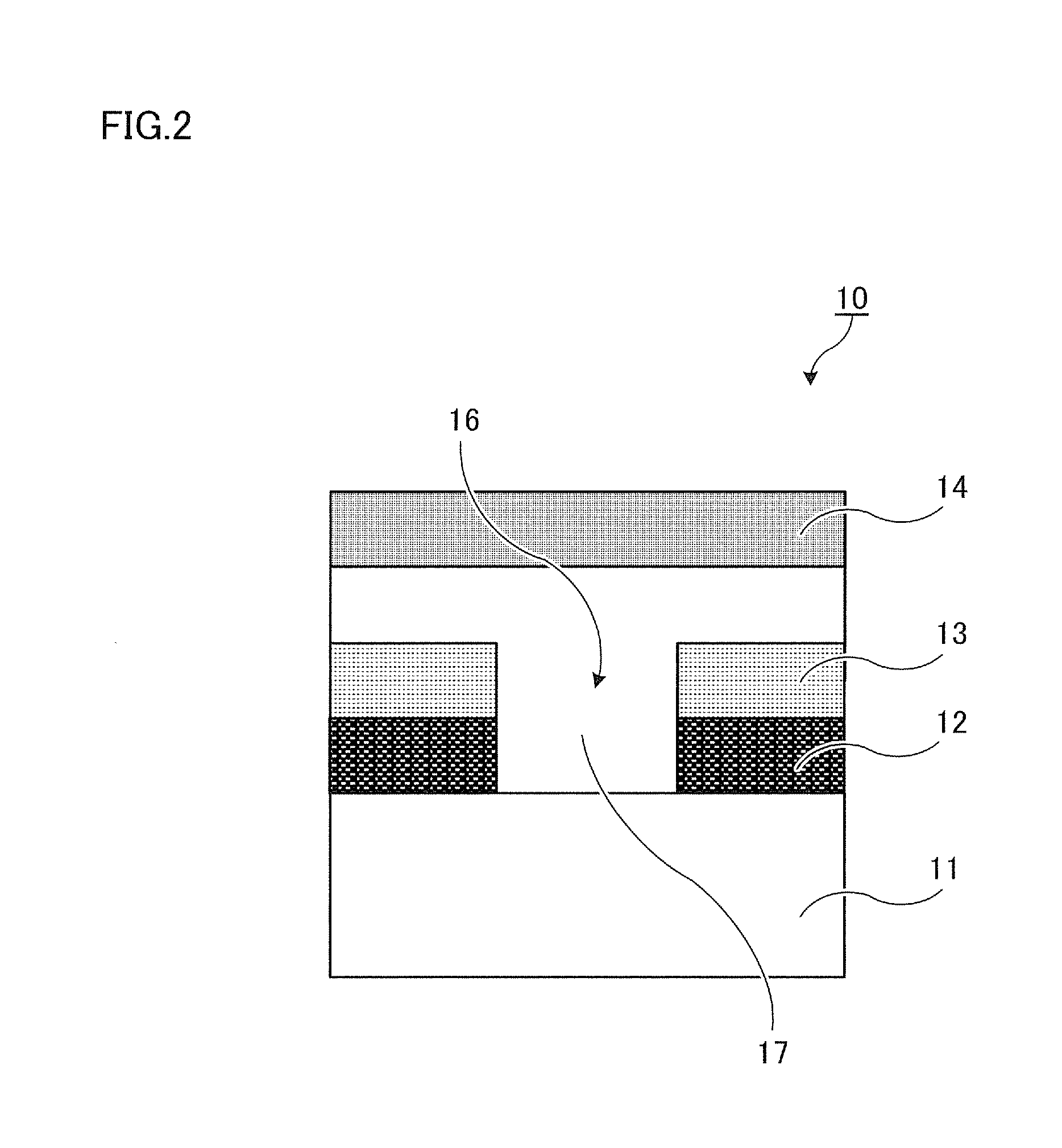
[0036]FIG. 1 is a diagram for illustrating the first exemplary embodiment of a light-emitting device 10 in the present exemplary embodiment. FIG. 2 is a partial cross-sectional view for illustrating a specific example of the light-emitting device 10 shown in FIG. 1. Hereinafter, the light-emitting device 10 will be explained with reference to FIGS. 1 and 2.
10>
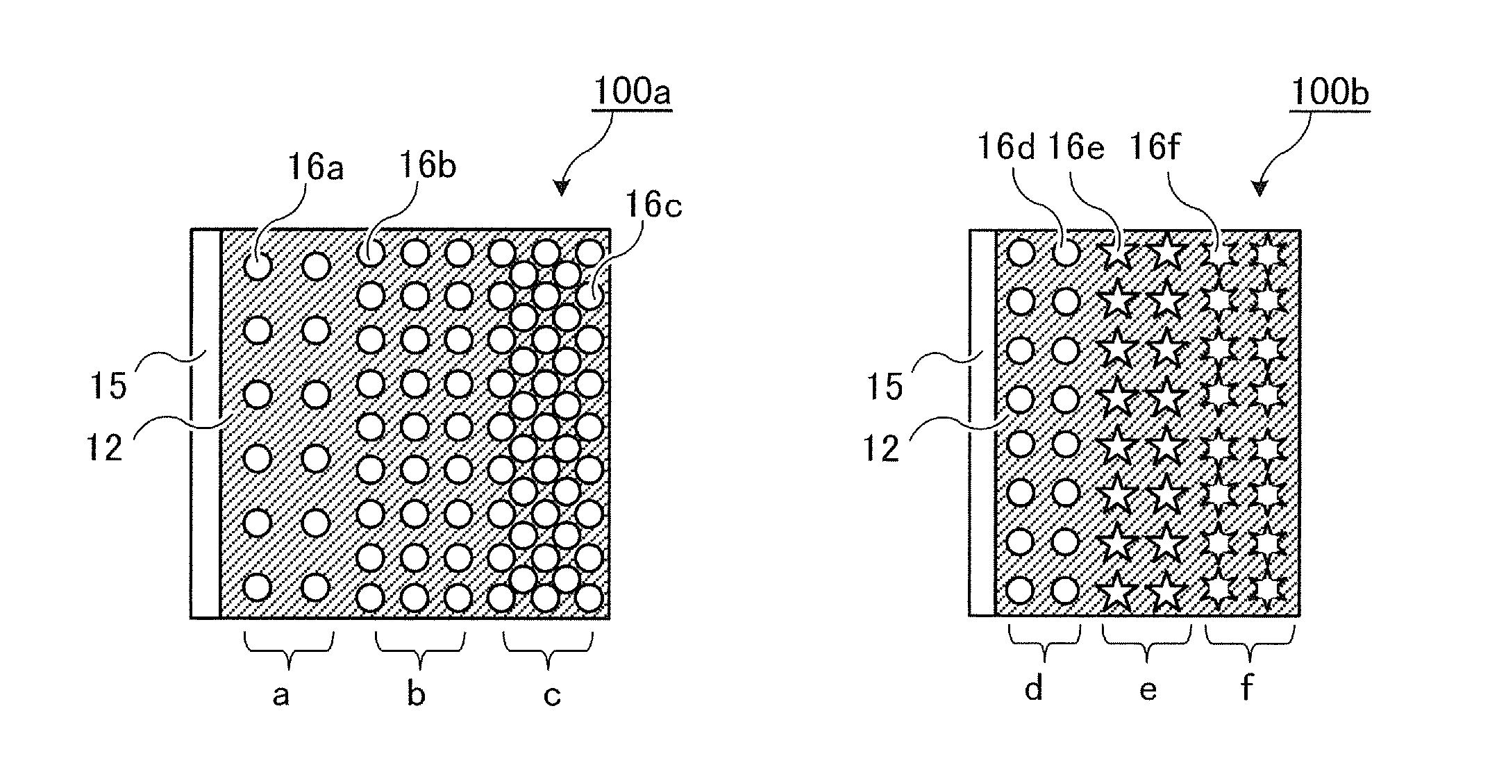
[0037]In the light-emitting device 10, a substrate 11, an anode layer 12 as a first electrode layer for injecting holes, which is formed on the substrate 11 in the case where the substrate 11 side is assumed to be the downside, and a dielectric layer 13 that is formed on the anode layer 12 and has an insulating property are stacked in order. Moreover, a concave portion 16 that passes through the anode layer 12 and the dielectric layer 13 is formed. Further, a light-emitting portion 17 that is formed successively from an upper surface of the dielectric layer 13 to an inner surface of the concave portion 16 and includes a light-e...
second exemplary embodiment
[0145]FIG. 8 is a diagram for illustrating the second exemplary embodiment of a light-emitting device in the present exemplary embodiment.
[0146]In a light-emitting device 20 shown in FIG. 8, a substrate 21, an anode layer 22 as a first electrode layer for injecting holes, which is formed on the substrate 21 in the case where the substrate 21 side is assumed to be the downside, and a dielectric layer 23 that is formed on the anode layer 22 and has an insulating property are stacked in order, which is the same as in the light-emitting device 10 (refer to FIG. 1). Moreover, similarly to the light-emitting device 10, plural concave portions 26 that pass through the anode layer 22 and the dielectric layer 23 are formed, and a light-emitting portion 27 that is formed successively from an upper surface of the dielectric layer 23 to an inner surface of the concave portion 26 is formed. On an upper part of the light-emitting portion 27, a cathode layer 24 as a second electrode layer for inje...
example 1
Preparation of Light-Emitting Material Solution
(Synthesizing of a Phosphorescent Light-Emitting Polymer Compound)
[0151]A phosphorescent light-emitting polymer compound (A) was prepared in accordance with the method disclosed in the paragraph [0077] of International Publication No. WO2010-016512. The weight-average molecular weight of polymer compound (A) was 52000, and molar ratio of each repeating unit was k:m:n=6:42:52.
[Chemical Formula 1]
[0152]
[0153]A light-emitting material solution (hereinafter, also referred to as “solution A”) was prepared by dissolving 3 parts by weight of the light-emitting polymer compound prepared (A) in 97 parts by weight of toluene.
[Preparation of Organic Light-Emitting Element]
[0154]A light-emitting device 1 having the similar cross-sectional shape as shown in FIG. 2 was produced in accordance with the order shown in FIG. 7.
[0155]A glass substrate (=the substrate 11: 110 mm square, 1 mm in thickness) in which ITO film (=the anode layer 12: 150 nm in th...
PUM
 Abstract
Description
Claims
Application Information
 - R&D
- Intellectual Property
- Life Sciences
- Materials
- Tech Scout
- Unparalleled Data Quality
- Higher Quality Content
- 60% Fewer Hallucinations
Browse by: Latest US Patents, China's latest patents, Technical Efficacy Thesaurus, Application Domain, Technology Topic, Popular Technical Reports.
© 2025 PatSnap. All rights reserved.Legal|Privacy policy|Modern Slavery Act Transparency Statement|Sitemap|About US| Contact US: help@patsnap.com


