Method of inhibiting or controlling release of well treatment agent

a well treatment agent and release technology, applied in the direction of fluid removal, chemistry apparatus and processes, borehole/well accessories, etc., can solve the problems of reducing well productivity, contaminating other equipment and flow conduits, and difficult or impossible to remove tubing for servicing

Active Publication Date: 2015-08-11
BAKER HUGHES INC
View PDF45 Cites 23 Cited by
  • Summary
  • Abstract
  • Description
  • Claims
  • Application Information

AI Technical Summary

Benefits of technology

[0010]A microemulsion having an incorporated well treatment agent provides for the slow and controlled release of the well treatment agent in a well, subterranean formation penetrated by a well, flow conduit, or vessel. Release of the well treatment agent into the well, formation, flow conduit, or vessel may be delayed until the time that the effect imparted by the well treatment agent is needed.

Problems solved by technology

The nature of these fluids, combined with the severe conditions of heat, pressure, and turbulence to which they are often subjected, are contributory factors to the formation and deposition of contaminants, such as scales, salts, paraffins, corrosion, bacteria and asphaltenes in production wells.
The formation and deposition of such contaminants may reduce well productivity.
Further, the presence of contaminants, such as scales, in the annulus may make it difficult or impossible to remove the tubing for servicing.
In addition, such contaminants form in other equipment and flow conduits used in the production of oil, gas and other fluids.
Acute problems result when such contaminants develop in equipment and flow conduits used in gas and oil production, refineries and other fluid processing facilities.
The formation and deposition of such unwanted contaminants decrease permeability of the formation and reduce well productivity and can completely block the well tubular in severe cases.
While breakers are typically incorporated into the fracturing fluid, their activity is most desirably delayed until after the proppant is placed into the fracture.
It is desirable, however, that the breaker not be functional until break down of the filter cake is needed.
In particular, alternatives have been sought for delivering well treatment agents into targeted areas such that the well treatment agent may be slowly released and the activity of the treatment agent may be delayed.

Method used


Image

  • Method of inhibiting or controlling release of well treatment agent
  • Method of inhibiting or controlling release of well treatment agent
  • Method of inhibiting or controlling release of well treatment agent

Examples


example 1

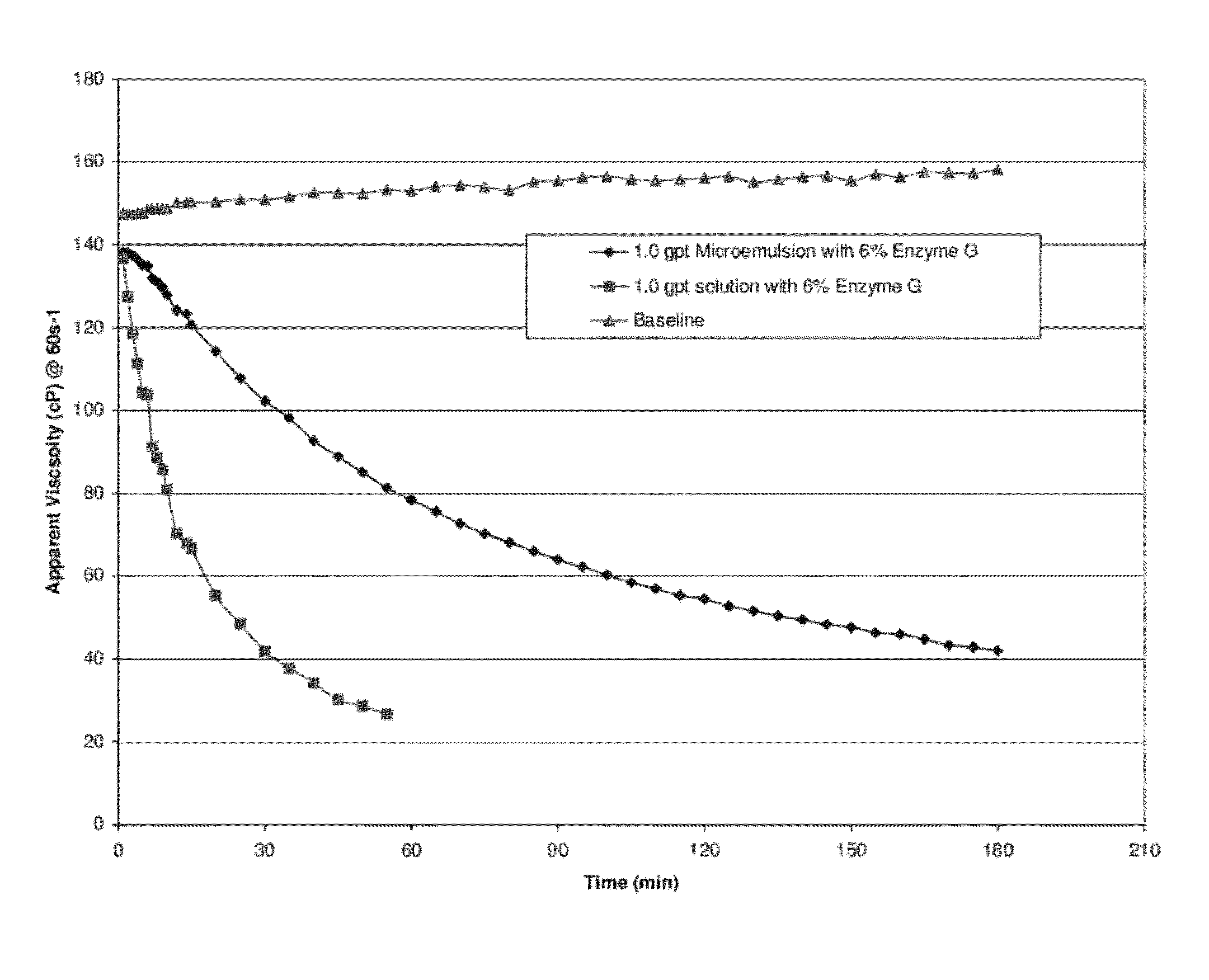
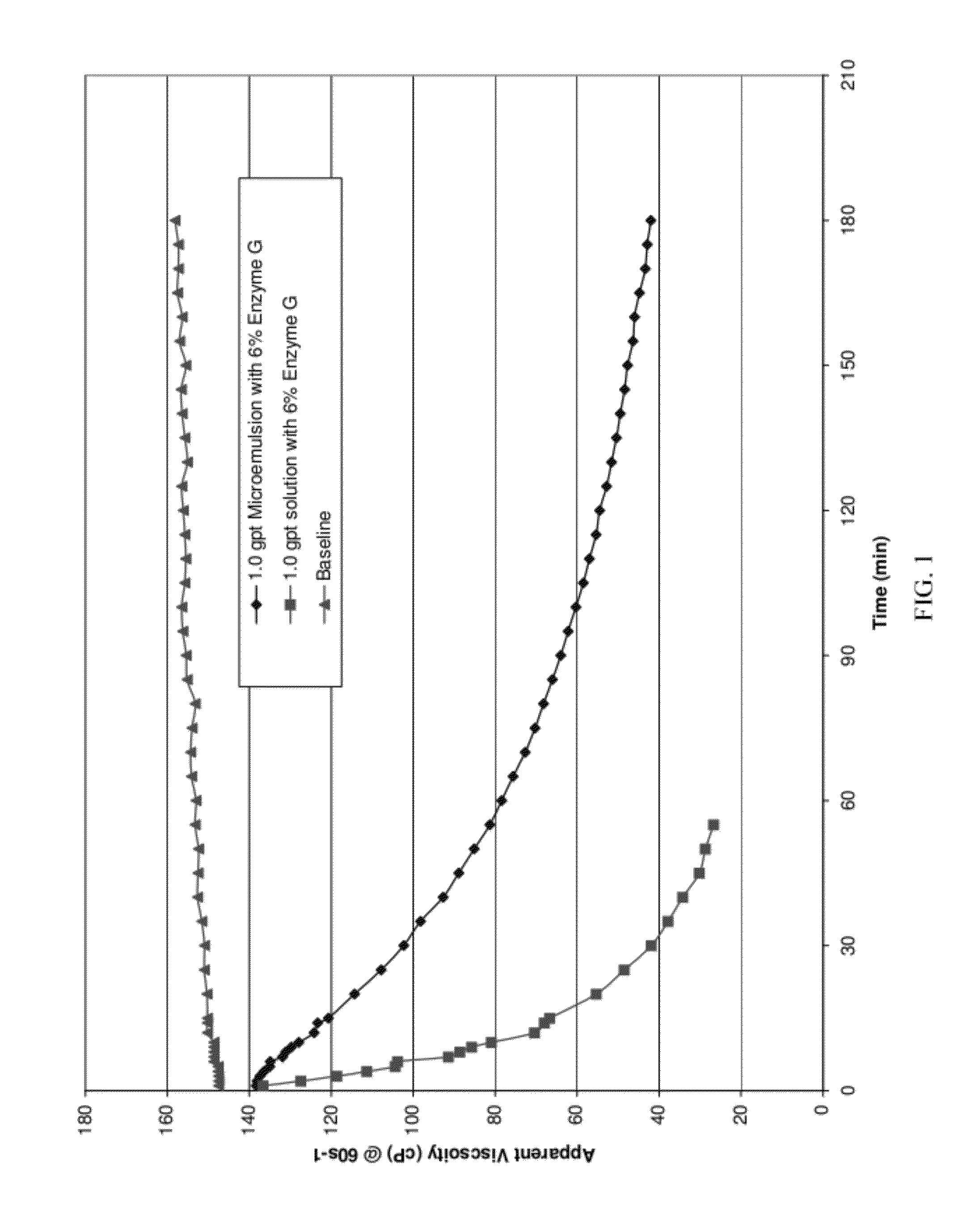
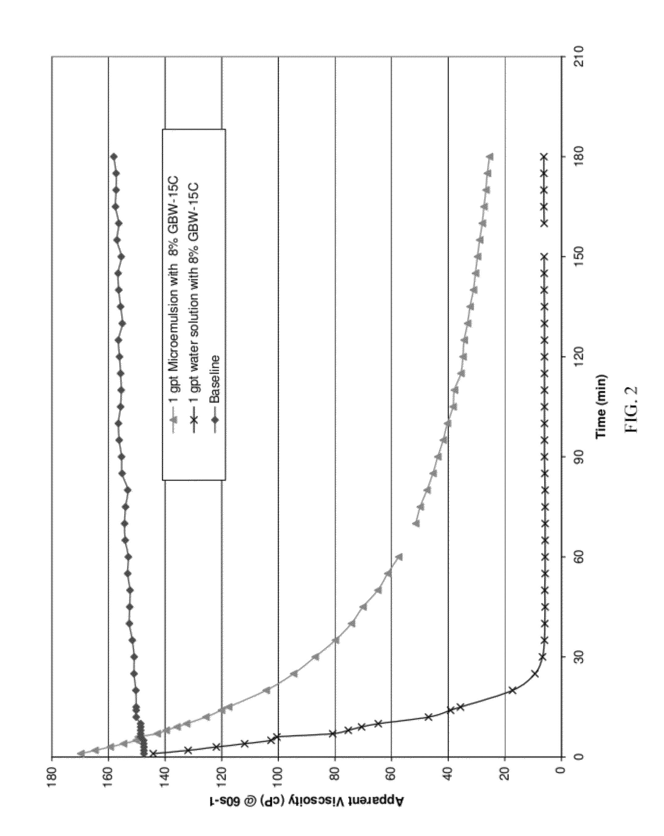
[0083]The release rate of water-in-oil microemulsions containing a beta-mannanase enzyme, commercially available as GBW-12CD from Baker Hughes Incorporated; Enzyme G, a breaker for guar based fluids, commercially available from Baker Hughes Incorporated and a hemicellulase, commercially available as Enzyme GBW-15C from Baker Hughes Incorporated were compared to aqueous fluids containing the same enzymes. The tests were conducted using the same concentrations at the same temperatures in order to demonstrate the effect of the well treatment agent in the water-in-oil microemulsion compared to the well treatment agent in an aqueous fluid. The oil phase of the microemulsion consisted of about 56% by volume of a surfactant mixture of polyoxyethylene sorbitan monopalmitate and ethoxylated castor oil and about 34% by volume d-limonene. The microemulsions contained 6% Enzyme G, 8% Enzyme GBW-15C. Water solutions containing 6% Enzyme G and 8% Enzyme GBW-15C were also prepared.

[0084]The linear...


PUM

PropertyMeasurementUnit
timeaaaaaaaaaa
particle sizeaaaaaaaaaa
weight percentaaaaaaaaaa

Abstract

A microemulsion delivery system containing a well treatment agent in a water-in-oil microemulsion may be used for well remediation as well as in other treatment operations including stimulation, acidizing, and drilling. In addition, the water-in-oil microemulsion delivery system may be used to clean surface equipment and downhole equipment.

Description

FIELD OF THE INVENTION[0001]The invention relates to a method of inhibiting or controlling the rate of release of a well treatment agent in a subterranean formation, an oil well, a gas well, a geothermal well, a flow conduit or vessel by introducing into the formation, well, flow conduit or vessel a microemulsion containing the well treatment agent.BACKGROUND OF THE INVENTION[0002]In the treatment of oil, gas and geothermal wells and / or subterranean formations penetrated by wells, it is important that well treatment agents be delivered into defined targeted areas. Well fluids are generally complex mixtures of aliphatic hydrocarbons, aromatics, hetero-atomic molecules, anionic and cationic salts, acids, sands, silts, clays and a vast array of other components. The nature of these fluids, combined with the severe conditions of heat, pressure, and turbulence to which they are often subjected, are contributory factors to the formation and deposition of contaminants, such as scales, salt...

Claims


Application Information

Patent Timeline
Patent Type & Authority Patents(United States)
IPC IPC(8): C09K8/52C09K8/60C09K8/36C09K8/28C09K8/035
CPCC09K8/035C09K8/28C09K8/36C09K8/52C09K8/602C09K2208/24
Inventor CAWIEZEL, KAY E.GUPTA, D. V. SATYANARAYANA
Owner BAKER HUGHES INC
Why Eureka
Try Eureka