Eureka AIR delivers breakthrough ideas for toughest innovation challenges, trusted by R&D personnel around the world.

Method for controlling the limiting of the rotational speed of a combustion engine

a technology of rotational speed and combustion engine, which is applied in the direction of machines/engines, automatic control of ignition, speed sensing governors, etc., can solve the problem of not being able to hold the current rotational, and achieve the effect of reducing technical complexity

Active Publication Date: 2015-08-11
ANDREAS STIHL AG & CO KG
View PDF10 Cites 5 Cited by
  • Summary
  • Abstract
  • Description
  • Claims
  • Application Information

AI Technical Summary

Benefits of technology

[0007]It is an object of the invention to provide a method which effects the switching off of a rotational speed lock circuit with little technical complexity.
[0010]Thus, without relatively great technical complexity, the ability to deactivate the rotational speed lock circuit as soon as the operator fully opens the throttle is provided.
[0014]It can be advantageous to generate the operation change signal in dependence on the output signal of a pressure sensor in the crankcase or in the intake channel of the combustion engine. While idling, there are different pressure conditions in the intake channel than under full load, so that the pressure change is sufficient in order to conclude that the operating state of the combustion engine is different. If the operator applies full throttle, the pressure conditions will change significantly, for example, the negative pressure in the intake channel and / or in the crankcase will drop greatly, which indicates the change of the operating mode of the combustion engine.

Problems solved by technology

This is possible when the operator applies full throttle with the rotational speed lock circuit switched on, so that the rotational speed open loop control unit runs out of its regulating range; the rotational speed open loop control unit is therefore not able to hold the current rotational speed of the combustion engine below the limit rotational speed of the rotational speed lock circuit in the full throttle position of the throttle flap.

Method used


Image

  • Method for controlling the limiting of the rotational speed of a combustion engine
  • Method for controlling the limiting of the rotational speed of a combustion engine
  • Method for controlling the limiting of the rotational speed of a combustion engine

Examples


Embodiment Construction

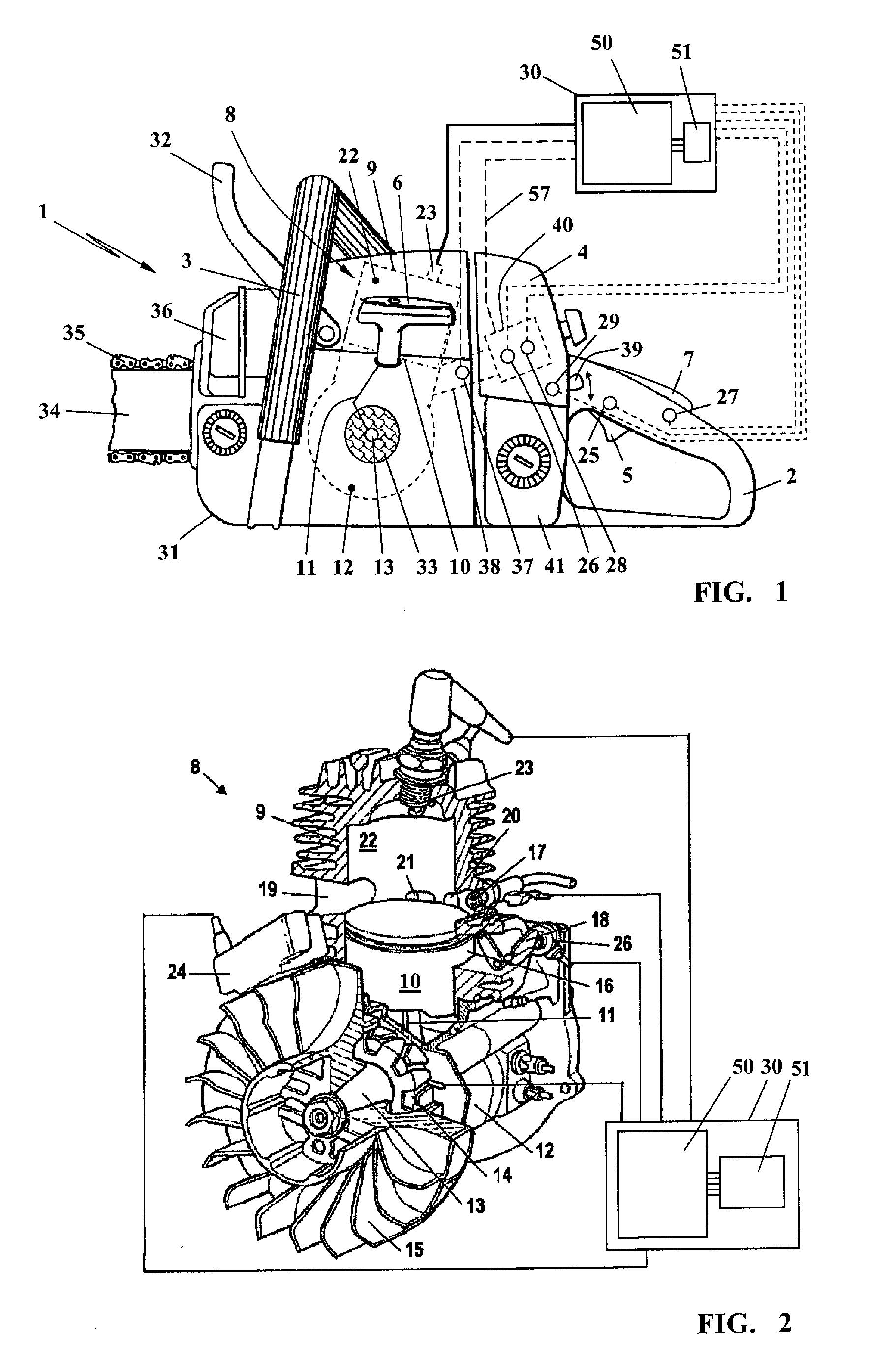
[0022]FIG. 1 schematically shows a chain saw as an example for a handheld work apparatus 1. This portable, handheld work apparatus 1 represents, by way of example, other portable, handheld work apparatuses 1 such as cut-off machines, hedge trimmers, brush cutters, pole pruners, blower apparatuses or the like.

[0023]The shown work apparatus 1 has a housing 31 which principally serves as the receptacle for a combustion engine 8. In the shown exemplary embodiment, the combustion engine 8 is a single cylinder two-stroke engine; a configuration as a single cylinder four-stroke engine can also be practical.

[0024]The work apparatus 1 has a back handle 2 arranged in the longitudinal direction of the housing 31 as well as a front, bale handle 3 which extends over the top side of the housing 31 transversely to the longitudinal direction of the housing 31. In the shown exemplary embodiment of a chain saw, a hand guard 32, which is configured as a trigger for a safety braking unit not shown, is ...


PUM


Abstract

A method controls the rotational speed limiting of an engine in a handheld work apparatus. The crankshaft of the engine drives a worktool via a clutch which engages in dependence on the motor rotational speed. Above an engaging speed of the clutch, a drive connection with the crankshaft is made and below the engaging speed, the drive connection is interrupted. A speed control unit monitors the rotational speed of the engine and includes a rotational speed lock circuit which limits the speed to a limit below the engaging speed. During the start of the engine, the lock circuit is switched on; it is switched off after the engine has been taken into operation when a deactivation signal is present, wherein the deactivation signal is generated when an operation change signal of the work apparatus is detected.

Description

CROSS REFERENCE TO RELATED APPLICATION[0001]This application claims priority of German patent application no. 10 2011 010 069.5, filed Feb. 1, 2011, the entire content of which is incorporated herein by reference.FIELD OF THE INVENTION[0002]The invention relates to a method for controlling the limiting of the rotational speed of a combustion engine in a handheld work apparatus.BACKGROUND OF THE INVENTION[0003]Portable, handheld work apparatuses such as chain saws, cut-off machines, hedge trimmers, blower apparatuses or the like are usually driven by a combustion engine which on location has to be taken into operation via a starting unit. Prior to the activation of the starting unit, which, for example, can be a pull starter, the combustion engine is placed into a starting mode, that is the fuel supply and the combustion air supply are set correspondingly. This can, for example, be done by adjusting a choke flap or a throttle flap in the intake channel.[0004]When the combustion engin...

Claims


Application Information

Patent Timeline
Patent Type & Authority Patents(United States)
IPC IPC(8): E21B4/04F02B63/02F02D31/00F02P5/145
CPCF02B63/02F02D31/009
Inventor GWOSDZ, FABIANNAEGELE, CLAUS
Owner ANDREAS STIHL AG & CO KG
Why Eureka
Eureka Blog
Learn More