Electric machine for a motor vehicle and method for cooling an electric machine

a technology for electric machines and motor vehicles, applied in the direction of electric propulsion parts, electric propulsion mounting, transportation and packaging, etc., can solve the problems of inability to correspondingly heat-controlled cooling fluids in particular situations, and high electric power loss of field coils of electric machines. , to achieve the effect of low technical complexity, low level of technical complexity and high speed

Active Publication Date: 2015-12-10
DR ING H C F PORSCHE AG
View PDF12 Cites 2 Cited by
  • Summary
  • Abstract
  • Description
  • Claims
  • Application Information

AI Technical Summary

Benefits of technology

[0012]The control unit may be designed to activate or deactivate the fan and / or the fluid supply depending on the speed and / or the torque. As a result, control of the different types of cooling can be realized with little technical complexity since the fan and / or the fluid supply merely needs to be switched on or off.
[0013]The control unit may be designed to activate the fan arrangement below a predefined speed of the electric machine. As a result, additional cooling power can be provided, for example, during runup of the motor vehicle when a high power loss occurs, with a low level of technical complexity.
[0014]The control unit may be designed to deactivate the fluid supply above a predefined speed and below a predefined torque of the electric machine. As a result, matching can be performed for high speeds and low torques when the electric machine has low electric power losses so that the energy consumption of the cooling of the electric machine can be reduced further.
[0015]The fluid line may be connected to a cooling circuit, and the control unit may be designed to control the cooling circuit in order to control the fluid supply. As a result, the cooling fluid supply can be controlled with little technical complexity.
[0016]The fan may designed to suck in ambient air and supply it to the electric machine as cooling air. As a result, cooling air can be provided with little technical complexity.
[0017]The fan may be designed to supply heated exhaust air from the electric machine to at least one component of the motor vehicle. As a result, the heated exhaust air can be used for heating the at least one component of the motor vehicle, such as, for example, an interior of the motor vehicle. Therefore, energy consumption in the motor vehicle can be reduced further and the efficiency can be increased further.

Problems solved by technology

The field coils of the electric machines can have a very high electric power loss in particular driving situations of a motor vehicle and therefore heat up considerably within a short period of time.
Cooling water cooling cannot provide sufficient cooling power in these situations.
Also, there may be no correspondingly heat-controlled cooling fluid available in particular situations, such as after starting the motor vehicle at high external temperatures.
However, the additional cooling of the electric machines for driving the motor vehicle has a high energy demand and thus the energy consumption of the motor vehicle is increased.
As a result, additional cooling power can be provided, for example, during runup of the motor vehicle when a high power loss occurs, with a low level of technical complexity.

Method used


Image

  • Electric machine for a motor vehicle and method for cooling an electric machine
  • Electric machine for a motor vehicle and method for cooling an electric machine

Examples


Embodiment Construction

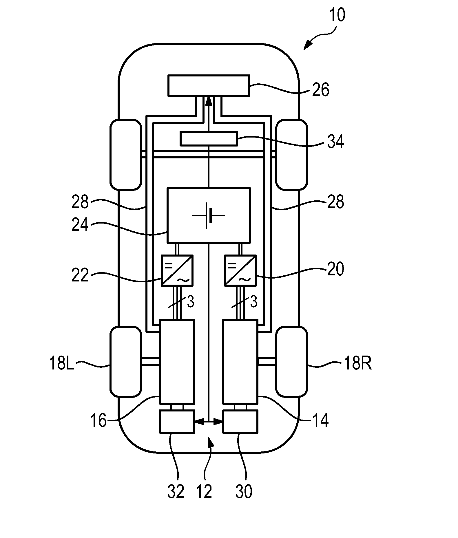
[0024]A motor vehicle in accordance with the invention is illustrated schematically in FIG. 1 and is denoted generally by the numeral 10. The motor vehicle 10 has a drive train 12, which in the present case contains two electric machines 14, 16 for providing drive power. The drive train 12 is used for driving driven wheels 18L, 18R of the motor vehicle 10. The electric machines 14, 16 provide a torque M to the driven wheels 18L, 18R and rotate with a speed n.

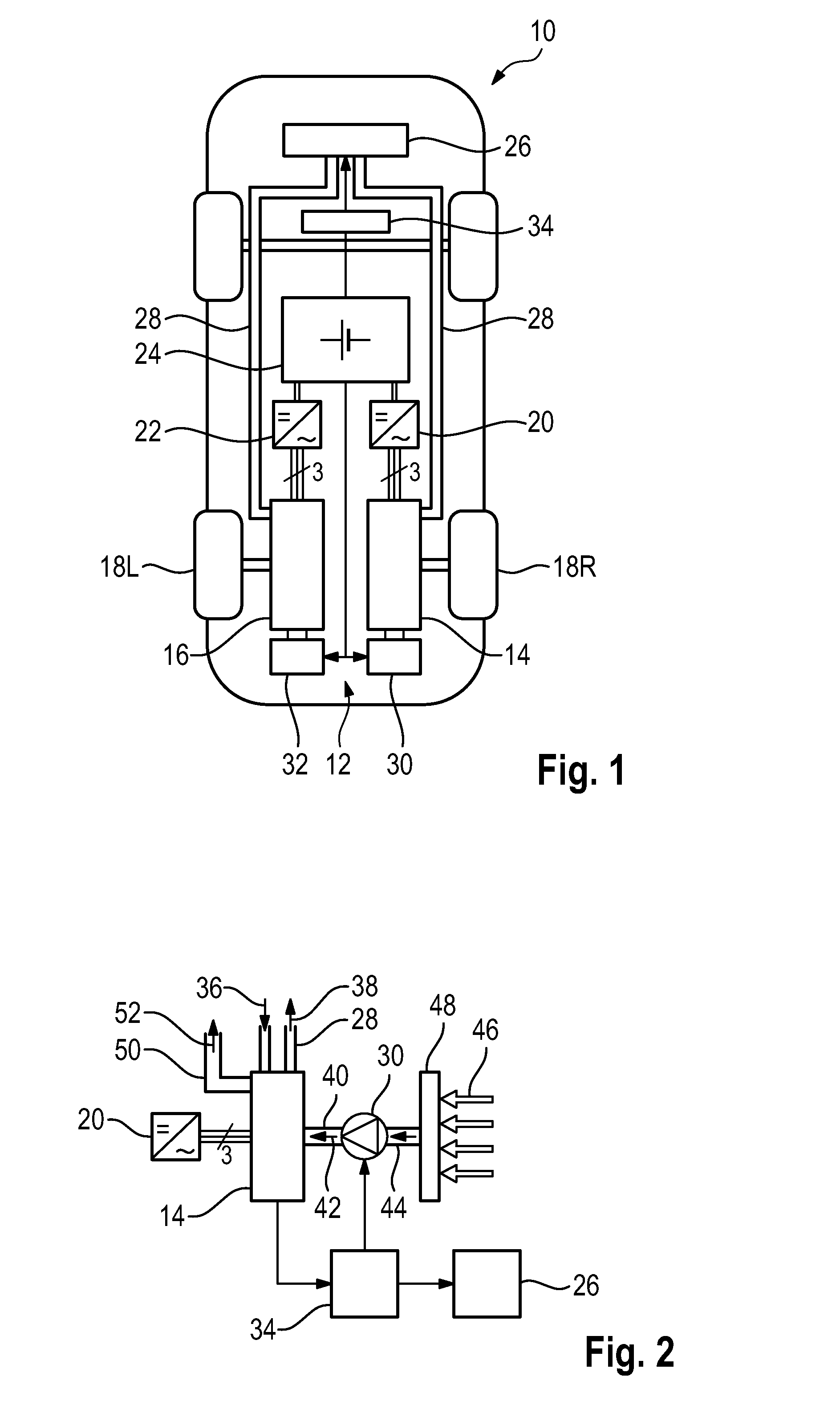
[0025]The electric machines 14, 16 are each connected to a DC voltage source 24 via an inverter 20, 22. The DC voltage source is in the form of a rechargeable battery 20. The inverters 20, 22 convert the DC voltage provided by the battery 24 or the provided direct current into in each case three-phase alternating current and correspondingly actuating or energizing the electric machines 14, 16.

[0026]In the embodiment of FIG. 1, the drive train 12 has only the two electric machines 14, 16 as drive assemblies. In an alternative emb...


PUM


Abstract

An electric machine (14, 16) for a drive train (12) of a motor vehicle (10) has a coil arrangement and a rotor mounted rotatably relative to the coil arrangement. A fluid line is connected thermally to at least one component of the electric machine (14,16) to supply a cooling fluid (36) to the electric machine (14, 16) and to cool the at least one component. A fan (30, 32) is designed to supply cooling air (42) to the electric machine for cooling the electric machine (14, 16), and a control unit (34) controls the fan (30, 32). The control unit (34) controls the fan arrangement (30, 32) and the cooling air supply depending on a speed (n) and/or a torque (M) of the electric machine (14, 16).

Description

CROSS REFERENCE TO RELATED APPLICATION[0001]This application claims priority under 35 USC 119 to German Patent Appl. No. 10 2014 108 100.5 filed on Jun. 10, 2014, the entire disclosure of which is incorporated herein by reference.BACKGROUND[0002]1. Field of the Invention[0003]The invention relates to an electric machine for a drive train of a motor vehicle, comprising a coil arrangement, a rotor mounted rotatably relative to the coil arrangement, a fluid line thermally connected to at least one component of the electric machine to supply a cooling fluid to the electric machine for cooling the at least one component of the electric machine, a fan to supply cooling air to the electric machine to cool the electric machine, and a control unit for controlling the fan. The invention also relates to a method for cooling such an electric machine of a motor vehicle. The invention further relates to a motor vehicle comprising a drive train with such an electric machine for providing drive pow...

Claims


Application Information

Patent Timeline
Patent Type & Authority Applications(United States)
IPC IPC(8): H02K9/04B60H1/02H02K9/19
CPCH02K9/04B60H1/02H02K9/19B60K11/06B60H1/00385B60H1/143B60K1/00B60K11/02B60K2001/006H02K2213/09
Inventor SCHIEK, WERNERSPIEGEL, LEOHINRICH, HOLGER
Owner DR ING H C F PORSCHE AG
Why Eureka
Try Eureka